Volkswagen Golf / Golf GTI / Golf Variant. Service manual - part 483


  Index      Volkswagen     Volkswagen Golf / Golf GTI / Golf Variant - service and repair manual 2013 year


Search            copyright infringement  


Content   ..  481  482  483  484   ..


Volkswagen Golf / Golf GTI / Golf Variant. Service manual - part 483


Fasteners

♦ Do not stretch the circlips.
♦ Installation position for some of the circlips: The circlip is »nar‐

rower at the top« and so is its installation position. This makes

it easier for the pliers to grab the circlip when removing and

installing it.

♦ Replace damaged or overstretched locking ring after remov‐

ing.

♦ The circlips must rest at the bottom of the groove.
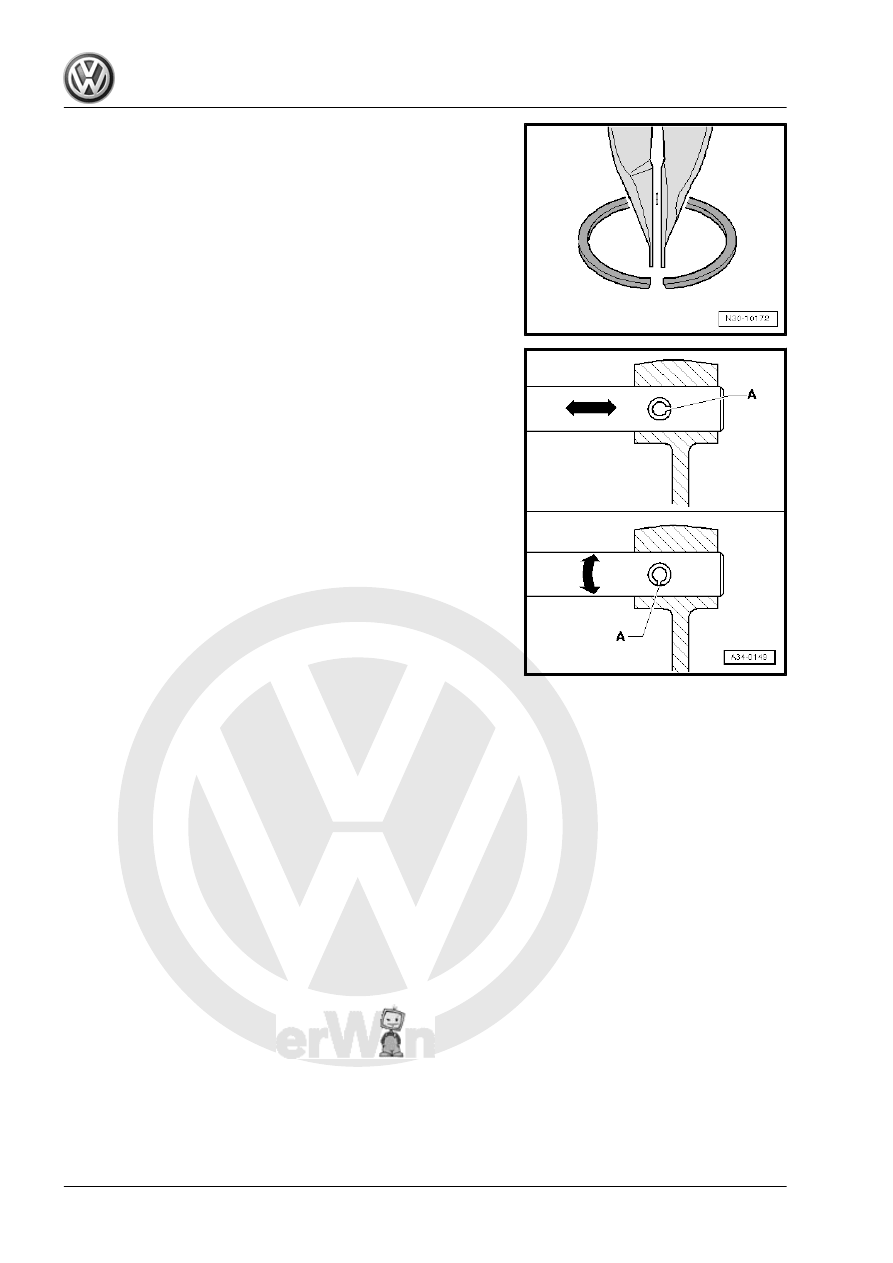
♦ Replace the adapter sleeves. Installation position: the slot

-A- should align with the line of force -arrow-.

Bolts and Nuts
♦ Always loosen or tighten bolts and nuts on covers and hous‐

ings diagonally with a tightening sequence.

♦ Especially delicate parts, such as clutch pressure plates, must

not be distorted. Loosen and tighten bolts and nuts in stages

in a diagonal sequence.

♦ The tightening specifications stated apply to non-oiled nuts

and bolts.

♦ Replace self-locking nuts and bolts after removing them.
♦ Make sure the contact surfaces and visible surfaces on the

nuts and bolts are waxed after assembling.

♦ Use a wire brush to clean the threads of the bolts that were

installed with locking fluid. Then insert the bolts with Locking

Fluid - AMV 185 101 A1- .

♦ If self-locking bolts were installed or if regular bolts were in‐

stalled with locking fluid, then the threaded holes must be

cleaned, for example with a thread tap. Otherwise the bolts

could shear the next time they are removed.

♦ Please make sure that the thread pitch is correct so that the

proper thread cutter is used during cleaning, and the thread

does not get damaged.

Bearings
♦ Insert the bearings with transmission fluid.
♦ Install the new tapered roller bearings. It is not necessary to

oil them.

♦ Install needle bearings with lettered side (thicker metal) racing

the fitting tool.

♦ Replace all the tapered roller bearings that are on the same

shaft. Use tapered roller bearings from the same manufactur‐

er.

♦ To install, warm the inner races/tapered roller bearing to ap‐

proximately 100 °C (212 °F) with -VAS6414- .

♦ Do not interchange outer and inner bearing races with those

from other bearing of the same size. The bearings are paired.

Adjusting Shims
♦ Measure the shims at several locations with a micrometer cal‐

iper. It is possible to measure the necessary shim thickness

by the different tolerances.

♦ Check for burrs and damage.
♦ Only install perfect shims.
Synchronizer Rings

♦ Do not interchange them. When reusing synchronizer rings,

always install to the same gear wheel.

♦ Check for wear and replace if necessary.
♦ Check the grooves -arrow 1- on the synchronizer ring -A- and

the inner race for flat areas (grooves are worn).

♦ The coating on the synchronizer rings must not be damaged.
♦ If an intermediate ring -B- is installed, check the intermediate

ring on the outer contact surface -arrow 2- and inner contact

surface -arrow 3- for grooves, scoring and blue coloring (from

overheating).

♦ Check taper of drive gear for grooves and scoring.
♦ Coat the synchronizing with transmission fluid and then install.
Toothed Gears, Synchronizer Hubs
♦ Clean before installing. Warm using the -VAS6414- to a max‐

imum 100 °C (212 °F).

♦ Pay attention to the installed location.
Selector Gears
♦ After assembling, check the selector gears for minimum axial

clearance and ease of movement.

Clutch
♦ Do not tilt the clutch pressure plate. Loosen and tighten it di‐

agonally and in small steps.

♦ To reduce odor caused by a burnt clutch, thoroughly clean the

clutch housing and the flywheel running surface with a clean

cloth.

3.2

Contact Corrosion

♦ The transmission housing and clutch housing consist of a

magnesium alloy.

♦ Bolts and other components, which come into direct contact

with the transmission, have a surface coating adapted for this.

♦ Contact corrosion occurs when incorrect components (bolts,

nuts, washers, etc.) are used. The transmission housing and

clutch housing are damaged.

♦ Only install components provided in the Parts Catalog.

4

Technical Data

⇒ “4.1 Transmission/Engine Allocation”, page 7
⇒ “4.2 Capacities”, page 8
⇒ “4.3 Gear Ratio Calculation”, page 8

4.1

Transmission/Engine Allocation

⇒ “4.1.1 Transmission/Engine Allocation, Golf”, page 7
⇒ “4.1.2 Transmission/Engine Allocation, Golf Wagon”,

page 7

4.1.1

Transmission/Engine Allocation, Golf

Manual Transmission

6-Speed 02Q

Codes

NBL

PFN

Manufactured

from

through

06/2014

03/2014

Allocation

Engine

2.0L - 155 KW

2.0L - 110 KW

Turbo diesel

Ratio

Z1 : Z2

Final drive I 

1)

68 : 21 = 3.238

69 : 20 = 3.450


Final drive II 

2)

68 : 26 = 2.615

69 : 25 = 2.760

Driveshaft Flange Diameter

107 mm

107 mm

1)

 Final drive for 1st through 4th gear

2)

 Final drive for 5th gear, 6th gear and reverse gear

• Refer to the Parts Catalog for the following information:
♦ The individual gear ratios
♦ Transmission fluid specification
♦ Clutch plate and pressure plate allocation

4.1.2

Transmission/Engine Allocation, Golf Wagon

Manual Transmission

6-Speed 02Q

Codes

PFN

Manufactured

from

through

03/2014


Allocation

Engine

2.0L - 110 KW

Turbo diesel


Ratio

Z1 : Z2

Final drive I 

1)

69 : 20 = 3.450


Final drive II 

2)

69 : 25 = 2.760


Driveshaft Flange Diameter

107 mm


1)

 Final drive for 1st through 4th gear

2)

 Final drive for 5th gear, 6th gear and reverse gear

• Refer to the Parts Catalog for the following information:
♦ The individual gear ratios
♦ Transmission fluid specification
♦ Clutch plate and pressure plate allocation


Content   ..  481  482  483  484   ..