Volkswagen Golf / Golf GTI / Golf Variant. Service manual - part 427


  Index      Volkswagen     Volkswagen Golf / Golf GTI / Golf Variant - service and repair manual 2013 year


Search            copyright infringement  


Content   ..  425  426  427  428   ..


Volkswagen Golf / Golf GTI / Golf Variant. Service manual - part 427


Caution

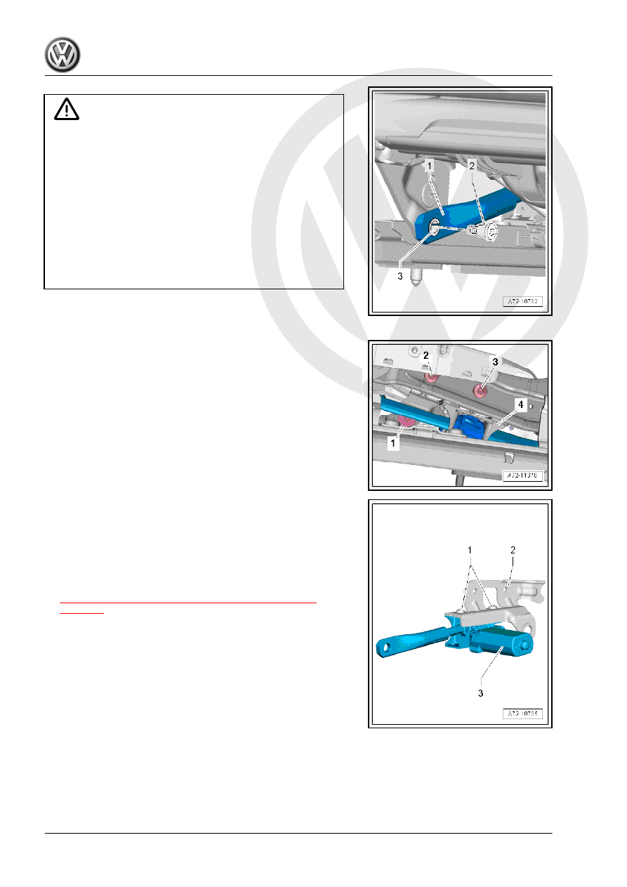
Threaded hole in the seat pan damaged or destroyed.

♦ The bolt -2- has left-hand thread.
♦ When removing or installing, the adjusting spindle/seat

pan threaded connection must be relieved. To do so, a

second technician must be pushing down on the seat

backrest.

Risk of damage to the bushing -3- in the bearing point (adjust‐

ing spindle/seat pan bolting).

♦ The bushing cannot be replaced with workshop materials.
♦ If the bushing is damaged, the corresponding assembly

parts must be replaced.

– Remove bolt -2- on the seat height adjustment motor adjusting

spindle -1-.

– Remove bolt -1- for seat angle adjustment motor adjusting

spindle (preset by the manufacturer).

– Move the upper seat frame as far upward as possible and

support with a suitable wood block on the Engine/Transmis‐

sion Holder - Seat Repair Fixture - VAS6136- .

– Remove the bolts -2- and -3-.
– Remove the fixture with the height adjustment motor -4- from

the seat pan.

– Remove the bolts -1-.

– Remove the bracket -2- from the seat height adjustment motor

-3-.

Installing
Install in reverse order of removal.
Tightening Specifications
♦ Refer to

⇒ “2.6.2 Overview - Seat Height Adjuster, Power Seat”,

page 332

2.20

Seat Pan with Driver/Front Passenger

Seat Forward/Back Adjustment Motor -

V28- / -V31- , Removing and Installing

Removing
– Move front seat to the highest position possible to keep the

torsion bar tension as low as possible.

– Remove the front seat. Refer to

⇒ “2.10 Front Seat, Removing and Installing”, page 335

 .

– Remove the front seat belt latch. Refer to

⇒ “1.14 Front Seat Belt Latch, Removing and Installing”, page

120

 .

– Disconnect the connector on the seat forward/back adjust‐

ment motor.

– Unclip the wire from the seat pan and set aside.

Caution

Danger of damaging the threaded holes or the bushing in the

bearing points (connecting the upper/ lower frame).

♦ The bolt -3- has left-hand thread.
♦ A second technician must be pushing down on the seat

backrest when removing the following bolts.

– Remove the bolt -3-.
– Remove the bolts -2-.
– Remove the seat pan -1- from the lower frame -4-.

Caution

Risk of damage to the bushings -1- in the bearing points -2-

(seat pan threaded connection and lower frame).

♦ The bushings cannot be replaced with workshop materi‐

als.

♦ If the bushings are damaged, the seat pan must be re‐

placed.

Installing
Install in reverse order of removal.
Tightening Specifications
♦ Refer to 

⇒ “2.5.2 Overview - Seat Pan, Power”, page 328

2.21

Backrest Adjuster, Removing and Instal‐

ling

⇒ “2.21.1 Backrest Adjuster, Removing and Installing, Except

Power Seat”, page 358
⇒ “2.21.2 Backrest Adjuster, Removing and Installing, Power

Seat”, page 358

2.21.1

Backrest Adjuster, Removing and Instal‐

ling, Except Power Seat

Note

The following describes the removing and installing on the left

side of the vehicle. Removing and installing on the right side is

identical.

Special tools and workshop equipment required
♦ Assembly Tool - 3399-
Removing
– Turn the backrest adjuster -1- until the retainer can be seen

from the rear -arrow A-. Use a flashlight if necessary.

– Insert the Assembly Tool - 3399- and lift it in the direction of

-arrow B-.

– Turn the backrest adjuster 120° farther.
– Insert the Assembly Tool - 3399- and lift it in the direction of

-arrow B-.

– Remove the backrest adjuster.
Installing
Install in reverse order of removal while paying attention to the

following:
– Note the correct installation position of the backrest adjuster.
– Pull on the backrest adjuster to make sure it is secure.
– Replace the backrest adjuster if it is too loose after assem‐

bling.

2.21.2

Backrest Adjuster, Removing and Instal‐

ling, Power Seat

The Driver Backrest Adjustment Motor - V45- / Front Passenger

Backrest Adjustment Motor - V46- cannot be replaced separately.

If the backrest adjuster is faulty, the backrest frame must be re‐

placed.

2.22

Lumbar Support Adjuster, Removing

and Installing

Special tools and workshop equipment required
♦ Door Trim Pliers - 3392-

Note

The following describes the removing and installing on the left

side of the vehicle. Removing and installing on the right side is

identical.

Removing
– Remove the lumbar support adjusting lever -1- from the shaft

-2- using the Door Trim Pliers - 3392- .

Installing
Install in reverse order of removal while paying attention to the

following:
– Make sure the splines on the lumbar support adjusting lever

-1- align with the splines on the shaft -2-.

– Pull on it to make sure the lever is secure.

– Replace the adjusting lever if it is too loose after assembling.


Content   ..  425  426  427  428   ..