Volkswagen Golf / Golf GTI / Golf Variant. Service manual - part 393


  Index      Volkswagen     Volkswagen Golf / Golf GTI / Golf Variant - service and repair manual 2013 year


Search            copyright infringement  


Content   ..  391  392  393  394   ..


Volkswagen Golf / Golf GTI / Golf Variant. Service manual - part 393


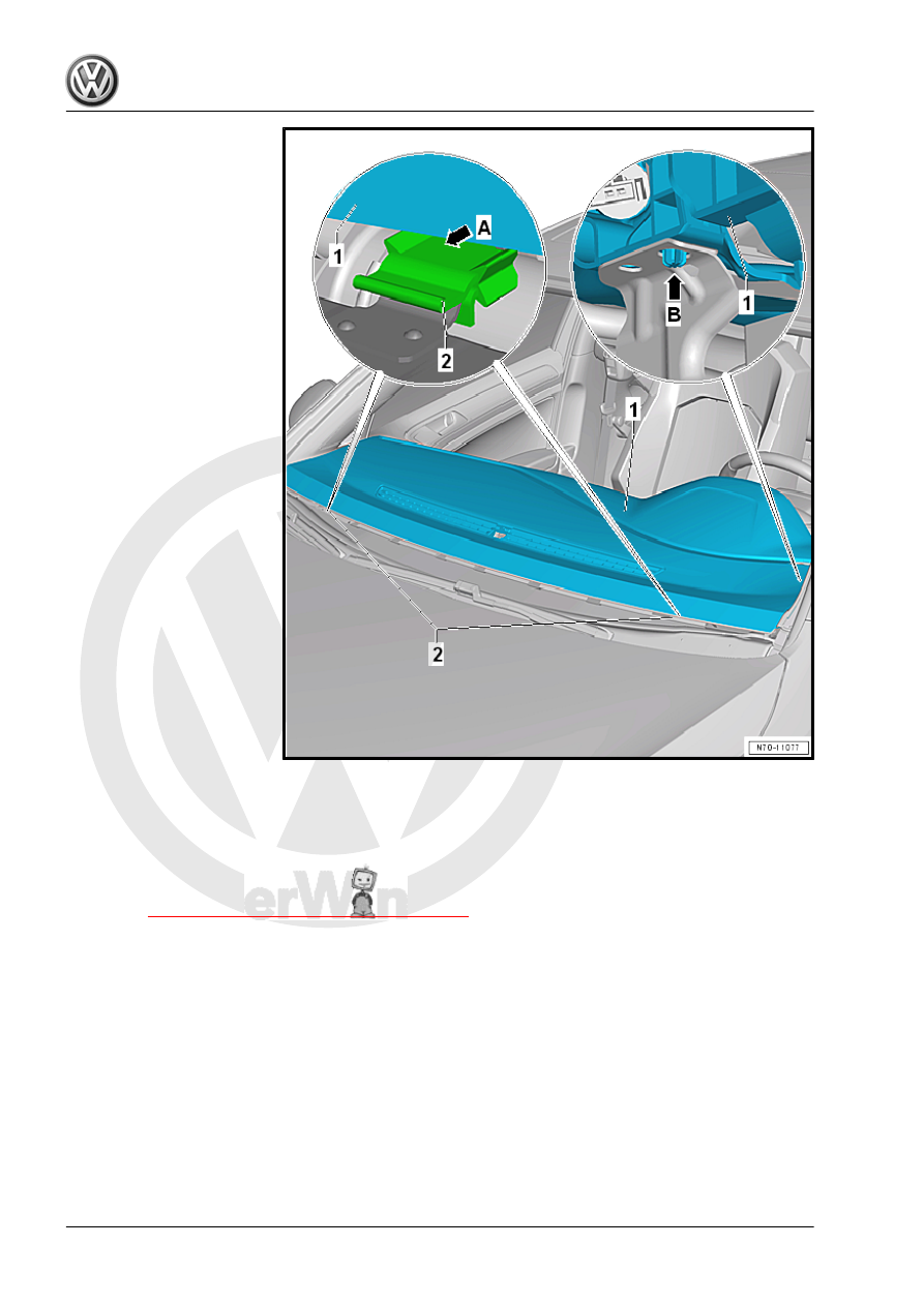
– Slide the instrument panel -1- into the mounts -2- in the wind‐

shield transition area -arrow A-.

– Insert the left and right guide tabs into the guide holes

-arrow B-.

Tightening Specifications
♦ Refer to 

⇒ “3.1 Overview - Instrument Panel”, page 210

3.7

Instrument Panel Vent, Removing and

Installing

Special tools and workshop equipment required
♦ Backrest Panel Tool - 3370-
♦ Trim Removal Wedge - 3409-

Removing
Side Instrument Panel Vent

Note

The removal and installation for the side instrument panel vent on

the driver side is described. The removal and installation for the

front passenger side is identical.

– Completely open the side instrument panel vent -1- using the

thumbwheel.

– Carefully guide the Backrest Panel Tool - 3370- -2- into the

center of the second slat from above and hook it in to the rear

of the vent -1-.

Note

The insertion depth of the Backrest Panel Tool - 3370- is 115 mm.

– Pull the side instrument panel vent out of the instrument panel

installation opening with a firm jerk.

Center Vent with Front Information Display Control Head - J685-

trim

Note

The center vent is removed together with the Front Information

Display Control Head - J685- trim.

Caution

The Front Information Display Control Head - J685- trim cannot

be removed as an individual part without being destroyed.

• Center vent is completely open at both thumbwheels.
• The vertical slats of the center vent are positioned in the di‐

rection of travel.

– Remove the display and control head trim. Refer to

⇒ “3.5 Display and Control Unit Trim, Removing and Instal‐

ling”, page 56

 .

– Grab the Front Passenger Airbag -Disabled- Indicator Lamp -

K145- -1- at the side -arrows A- and pull it out of the instrument

panel.

– Disconnect the connectors.

– Carefully guide a Backrest Panel Tool - 3370- in both the right

and left center vent -arrows-.

– Hook both Backrest Panel Tools - 3370- into the top end of the

corresponding fresh air duct.

Note

The insertion depth of the Backrest Panel Tool - 3370- is approximately 110 mm.

– Remove the center vent -1- including the installed trim -2- from

the instrument panel installation opening at the same time by

firmly tugging on the two Backrest Panel Tools - 3370- .

– Carefully unclip the trim -2- from the mounts in the instrument

panel -arrows- using the Trim Removal Wedge - 3409- .

Installing

Note

Check all the fasteners for damage and replace if necessary.

Install in reverse order of removal.

3.8

Side Defroster Vent, Removing and In‐

stalling

Note

The removal and installation for the side defroster vent on the

driver side is described. The removal and installation for the front

passenger side is identical.

Special tools and workshop equipment required
♦ Trim Removal Wedge - 3409-
Removing
– Pry the defroster vent -1- upward out of the instrument panel

installation opening using the Trim Removal Wedge - 3409-

and remove it.

Installing
Install in reverse order of removal.

3.9

Front Passenger Side Impact Absorber, Removing and Installing


Content   ..  391  392  393  394   ..