Volkswagen Golf / Golf GTI / Golf Variant. Service manual - part 320


  Index      Volkswagen     Volkswagen Golf / Golf GTI / Golf Variant - service and repair manual 2013 year


Search            copyright infringement  


Content   ..  318  319  320  321   ..


Volkswagen Golf / Golf GTI / Golf Variant. Service manual - part 320


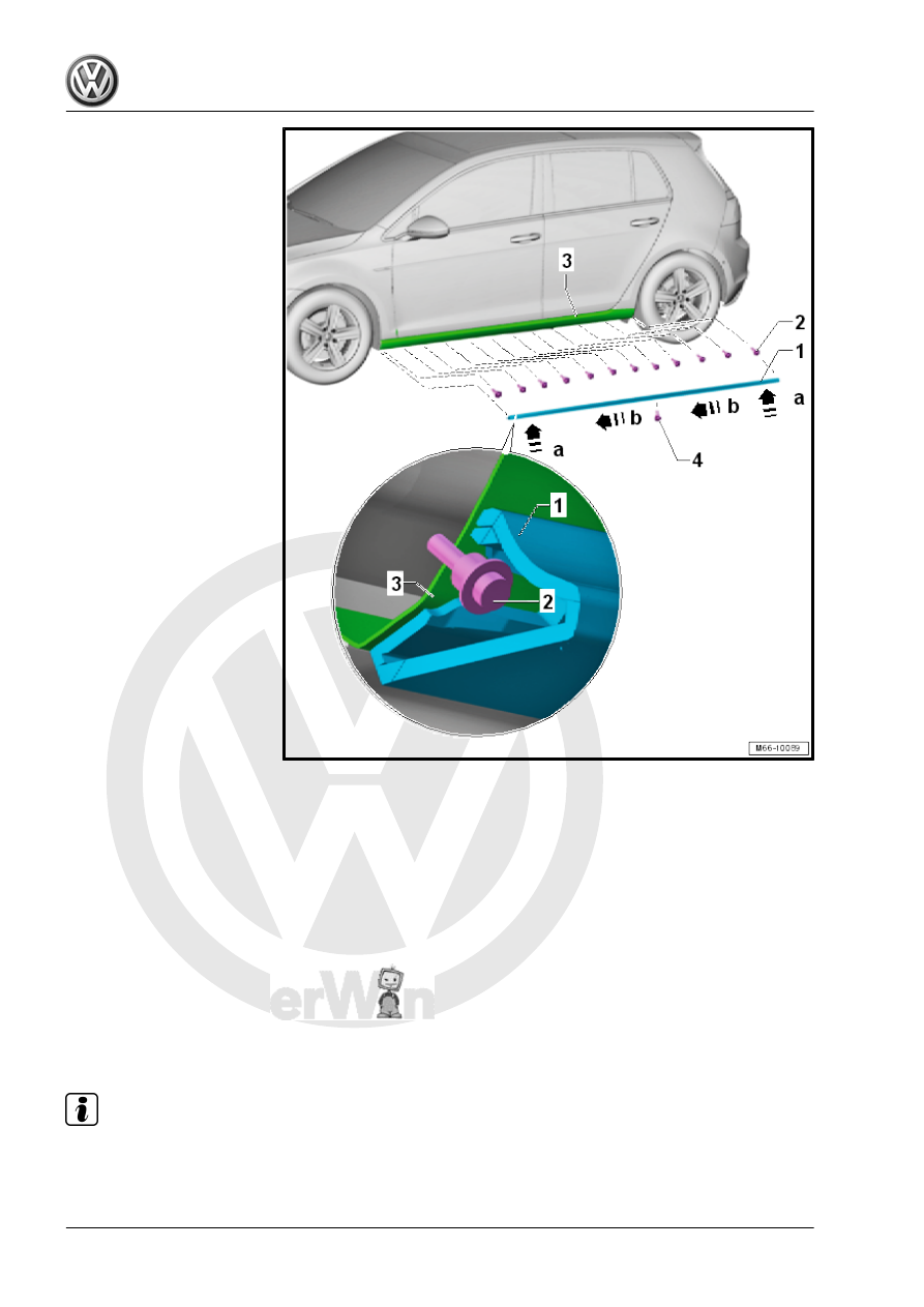
– Install the self-tapping bolts -2- until the thread engages.
– Tighten the bolts -2- only to the required tightening specifica‐

tion, so that they are not over tightened.

– Position the side sill trim panel -1- evenly in direction of

-a arrows- with the openings on the back over all of the screws

-2- until the side sill trim panel touches the side sill -3-.

Position the side sill trim panel with a second mechanic so that all

screws remain in the openings when molding is slid on.
– Push the side sill trim panel forward forcefully until stop in di‐

rection of -b arrows-.

– Install the exterior bolt -4- in the side sill trim panel.
Tightening Specifications
Dimensions

Note

The screws for the side sill trim panel are corrosion-resistant. Additional treatment is not necessary.

If a screw is overtightened, it must always be replaced with a “black” oversized screw.

– Measure the holes according to the table below.
– Punch the holes for the screws.
– Pre-drill the holes using a 1.5 mm drill.

Note

Dimension -a- is measured including the front wheel housing liner. Dimensions -b through I- are always

measured from the center hole outward.

Dimension -m- is only measured on a 4-door in the rear area.

For a 2-door vehicle, the dimension -m- must be aligned in height according to the front holes.

Dimensions Table

Dimension -a-

= 758 mm

Dimension -b-

= 713 mm

Dimension -c-

= 593 mm

Dimension -d-

= 453 mm

Dimension -e-

= 303 mm

Dimension -f-

= 152 mm

Dimension -g-

= 1028 mm

Dimension -h-

= 906 mm

Dimension -i-

= 755 mm

Dimension -j-

= 604 mm

Dimension -k-

= 453 mm

Dimension -l-

= 302 mm

Dimension -m-

= 50 mm

3.6

Front Door B-Pillar Trim, Removing and Installing

Note

The following describes the removal and installation of the left side. Removing and installing the right side is

identical.

Removing

– Lower the door window.
– Remove the window guide -3- in the area of the B-pillar trim

-1- from the door frame in direction of -arrow-.

– Unclip the expanding rivet -2-.
– Push the B-pillar trim -1- downward and remove from the door

frame.

– Remove the B-pillar trim -1- upward.
Installing
– Position the B-pillar trim -1- on the door frame.
– Guide the B-pillar trim -1- in at the bottom and position it.
– Push the B-pillar trim -1- upward until it touches the window

guide -3-.

– Clip in the expanding rivets -2- from the top to the bottom and

insert the window guide -3- in the B-pillar trim in direction of

-arrow-.

3.7

Rear Door B-Pillar Trim, Removing and Installing

Note

The following describes the removal and installation of the left side. Removing and installing the right side is

identical.

Removing


Content   ..  318  319  320  321   ..