Volkswagen Golf / Golf GTI / Golf Variant. Service manual - part 253
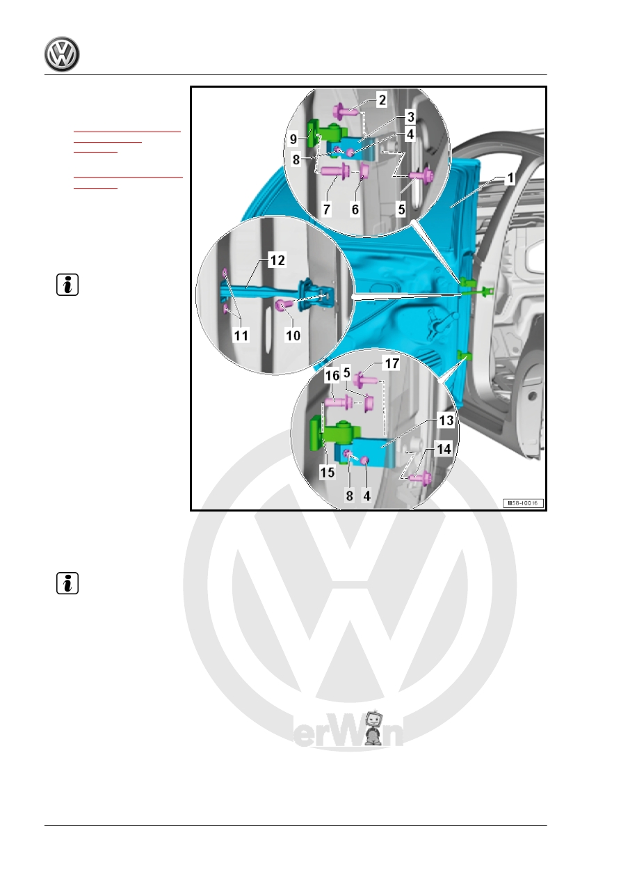
1 - Rear Door
❑ Removing and instal‐
ling. Refer to
❑ Adjusting. Refer to
2 - Bolt
❑ 50 Nm
❑ Loosening one time to
adjust the door is per‐
mitted. Always replace
afterward.
Note
♦
Another tightening specification
must be observed after replacing
the A-pillar.
♦
Tightening specification after re‐
placing the A-pillar: 20 Nm + 90°
3 - Door Hinge
❑ The hinge has two sec‐
tions.
❑ The bolt -8- attaches the
hinge lower section to
the upper section.
4 - Cap
❑ For the bolt -8-
5 - Bolt
❑ 50 Nm
❑ Loosening one time to adjust the door is permitted. Always replace afterward.
❑ Installed from the vehicle interior
❑ The B-pillar lower trim must be removed in order remove and install. Refer to ⇒ Body Interior; Rep. Gr.
70 ; Passenger Compartment Trim; B-Pillar Trim Panel, Removing and Installing .
Note
♦
Another tightening specification
must be observed after replacing
the A-pillar.
♦
Tightening specification after re‐
placing the A-pillar: 20 Nm + 90°
6 - Cap
❑ For the bolt -7-
7 - Bolt
❑ 50 Nm
❑ Loosening one time to adjust the door is permitted. Always replace afterward.
8 - Bolt
❑ 23 Nm
❑ Connects the hinge upper section to the hinge lower section