Volkswagen Golf / Golf GTI / Golf Variant. Service manual - part 206
• Vehicles with Auto. Transmission, ensure Selector Lever po‐
sition is in “P”.
• Vehicles with Man. Transmission, ensure Shifter Lever posi‐
tion is in “N” with Parking Brake applied.
• Coolant Temperature: ≥ 80° C.
• Observe all safety precautions:
⇒ “1.1 Safety Precautions”, page 2
• View clean working conditions:
⇒ “1.2 Clean Working Conditions”, page 3
.
• For Hybrid vehicles refer to:
⇒ “1.3 High Voltage System General Warnings”, page 4
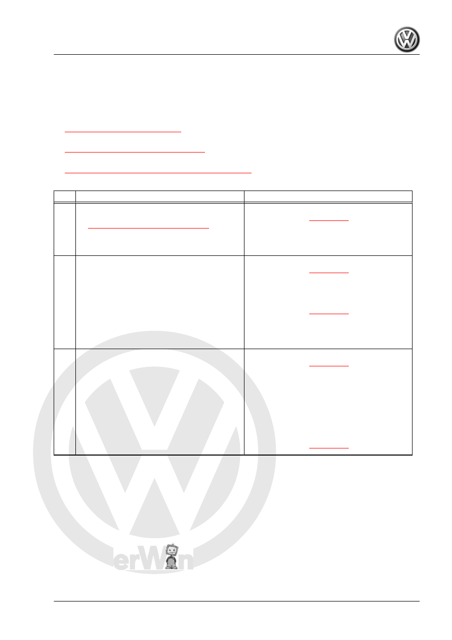
Test Procedure
Step
Procedure
Result / Action to Take
1
• PERFORM: Preliminary Check to verify the
customers complaint. Refer to
⇒ “3.1 Preliminary Check ”, page 18
– Was Complaint verified?
– YES:
– NO:
♦ GATHER more information from customer
about the complaint.
2
• IGNITION: OFF.
• REMOVE: Evaporative Canister. Refer to ap‐
propriate repair manual.
• Plug or Cap off the Fuel Tank Pressure Sensor
- G400- hose going to the vent filter.
• CONNECT: Hand vacuum pump to the Fuel
Tank Pressure Sensor - G400- and apply
0.700 bar and see if the vacuum holds.
– Did the vacuum hold?
– YES:
– NO:
♦ REPLACE: Fuel Tank Pressure Sensor -
G400- . Refer to appropriate repair manual.
3
• DISCONNECT: Fuel Tank Leak Detection
Control Module - J909 - harness connector.
• IGNITION: ON.
• CHECK: Fuel Tank Leak Detection Control
Module - J909 - harness connector terminal 4
to ground for voltage.
• IGNITION: OFF.
• SPECIFIED VALUE: Battery voltage.
– Was Value obtained?
– YES:
– NO:
♦ PERFORM: Visual Inspection of wiring and
component.
♦ CHECK: Wiring for open, high resistance,
short or harness connector for damage, corro‐
sion, loose or broken terminals.
♦ REPAIR: Faulty wiring or connector.
♦ GO TO: Step 5
GTI 2014 ➤
Generic Scan Tool - Edition 04.2015
3. Diagnosis and Testing
497