Volkswagen Golf / Golf GTI / Golf Variant. Service manual - part 56
12
Trailer Hitch
⇒ “12.1 Overview - Trailer Hitch Socket”, page 213
⇒ “12.2 Trailer Socket U10 ”, page 214
⇒ “12.3 Towing Recognition Control Module J345 , Removing
12.1
Overview - Trailer Hitch Socket
⇒ “12.1.1 Overview - Trailer Hitch Socket, Sedan”, page 213
⇒ “12.1.2 Overview - Trailer Hitch Socket, Wagon”, page 214
12.1.1
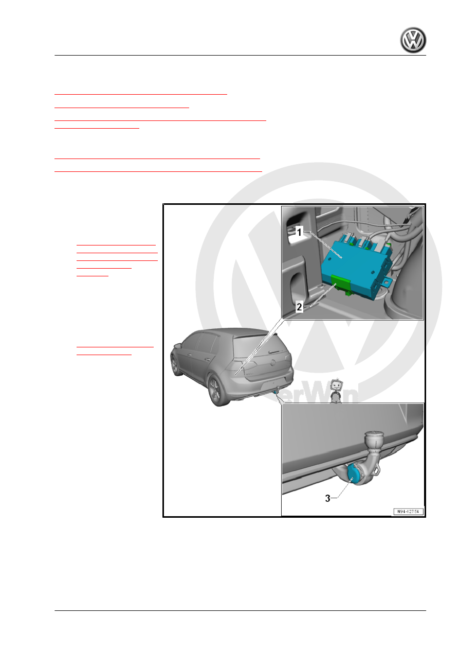
Overview - Trailer Hitch Socket, Sedan
1 - Towing Recognition Control
Module - J345-
❑ Removing and instal‐
ling. Refer to
.
2 - Frame
❑ For Towing Recognition
Control Module - J345-
3 - Trailer Socket - U10-
❑ Connector assignment.
Refer to
.