Volkswagen Golf / Golf GTI / Golf Variant. Service manual - part 50
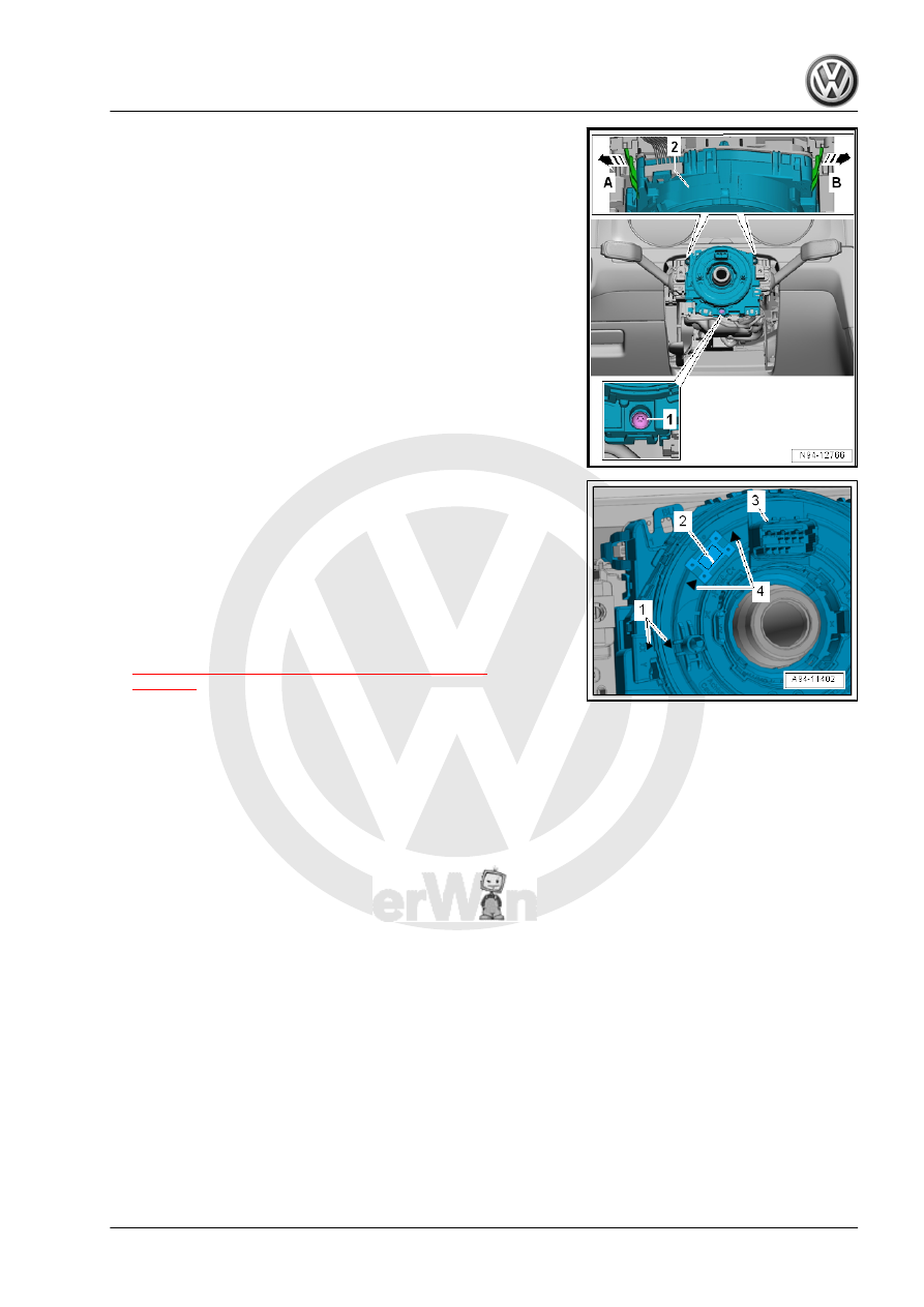
– Remove the Steering Column Electronics Control Module -
J527- -2- from the Steering Column Combination Switch -
E595- .
Installing
Install in the reverse order of removal while paying attention to
the following:
– Before sliding the Steering Column Electronics Control Mod‐
ule - J527- -3- the following must be checked.
♦ The “arrows” -1- must align.
♦ The spiral spring -2- must be seen in the window between the
“arrows” -4-.
– Make sure that all connectors are installed securely.
Tightening Specifications
♦ Refer to
⇒ “8.1 Overview - Steering Column Switch Module”,
8.6.2
Steering Column Electronics Control
Module - J527- , Removing and Instal‐
ling, Valeo
The Airbag Spiral Spring/Return Spring with Slip Ring - F138- is
integrated into the Steering Column Electronics Control Module -
J527- .
If the control module is being replaced, use the Vehicle Diagnostic
Tester and select the “Replacing” function for the respective con‐
trol module in “Guided Fault Finding”.
Removing
– Position the front wheels straight-ahead. The steering wheel
is located in the neutral position.
– Position the steering wheel as far back as possible. Use the
entire adjustment range of the steering column adjustment for
this.
– Remove the steering wheel. Refer to ⇒ Suspension, Wheels,
Steering; Rep. Gr. 48 ; Steering Wheel; Steering Wheel, Re‐
moving and Installing .
– Remove the lower steering column trim panel. Refer to ⇒ Body
Interior; Rep. Gr. 68 ; Storage Compartments and Covers;
Lower Steering Column Trim Panel, Removing and Installing .