Volkswagen Golf Variant / Jetta. Manual - part 222
 

  Index      Volkswagen     Volkswagen Golf Variant (2007), Jetta (2005) - service repair manual


Search            


Content   ..  220  221  222  223   ..


Volkswagen Golf Variant / Jetta. Manual - part 222


Note

♦

Allocate thrust plate and clutch disc according to the engine

code. Refer to the Parts Catalog.

♦

Check whether there are centering sleeves for the engine/

transmission in the cylinder block; install if necessary.

♦

If the alignment sleeves are missing, it will be difficult to shift,

there will be clutch problems and the transmission may make

noises (loose rattling).

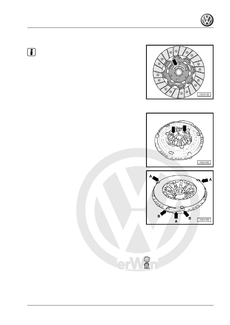
Clutch Plate Installed Position
• “Transmission side” label faces the transmission.

Check the Ends of the Diaphragm Spring
• Wear up to half the thickness of the diaphragm spring

-arrows- is permitted.

Checking the Spring Connections and Rivet Connections
– Check the spring connections -arrows A- for damage and

make sure the rivet connections -arrows B- are tight.

3. Clutch, Servicing, Diesel    

63

sure Plates
• Both edges -A- of the adjusting ring must be located between

both notches -arrows B-.

• If the adjusting ring takes on a different position with new pres‐

sure plates, pressure plate and clutch plate must not be in‐

stalled.

• With used clutches, the adjusting ring may take on a position

outside of the notches.

Note

♦

Replace clutch plates and pressure plates if the rivets are

damaged or loose.

♦

Replace the pressure plate and the clutch plate together.

♦

Allocate clutch disc and thrust plate using the engine code.

Refer to the Parts Catalog.

♦

Clean input shaft splines and (on used clutch plates) the hub

splines, remove corrosion and apply a very thin coating of

Grease for Clutch Disc Shaft Splines - G 000 100- to the

splines. Then move the clutch plate back and forth on the input

shaft until the hub moves freely on the shaft. Remove any ex‐

cess grease.

♦

The pressure plates are protected from corrosion and lubrica‐

ted. Only the running surfaces may be cleaned. Otherwise the

service life of the clutch will be shortened considerably.

♦

The pressure plate contact surface and the clutch plate lining

must completely touch the flywheel. Install the bolts.

– Move the Flywheel Retainer - 3067- during installation.

Engines having A Crankshaft with A Smaller Diameter -arrow-, or

Engines having A Needle Bearing -arrow- in the Crankshaft

64

Plate on Engines with A Crankshaft with A Smaller Diameter, or

Engines with A Needle Bearing in the Crankshaft.

Note

Ignore arrows -A and B-.

Continuation for All
– Position the pressure plate on the centering pins.
– Install all the bolts evenly, by hand, until the bolt heads contact

the pressure plate.

– Tighten the bolts in small steps and in diagonal sequence to

prevent damaging the centering holes of the pressure plate

and the centering pins of the dual mass flywheel -item 4-

⇒ Item 4 (page 66)

 .

– Install the transmission.

3.5

Clutch, Servicing, “LuK”

1 - Dual Mass Flywheel

❑ Removing and instal‐

Gr.  13 .

❑ Make sure it fits secure‐

ly on the centering pins

❑ Keep the clutch lining

contact surface free of

grooves, oil and grease.

2 - Clutch Plate

❑ Allocation. Refer to the

Parts Catalog.

❑ Removing and instal‐

ling. Refer to

⇒ “3.4  LuK Clutch, Re‐

moving and Installing”,

page 62

 .

❑ Only replace together

with the SAC pressure

plate

❑ Installation position. Re‐

fer to

⇒ Fig. ““Clutch Plate In‐

stalled Position”“ ,

page 63

3 - SAC Pressure Plate

❑ SAC = “Self Adjusting

Clutch”

❑ Only replace together

with the clutch plate

❑ Allocation. Refer to the

Parts Catalog.

❑ Removing and instal‐

ling. Refer to

⇒ “3.4  LuK Clutch, Re‐

moving and Installing”,

page 62

 .

3. Clutch, Servicing, Diesel    

65

⇒ Fig. ““Check the Ends of the Diaphragm Spring”“ , page 63

❑ Checking the spring connections and rivet connections. Refer to

⇒ Fig. ““Checking the Spring Connections and Rivet Connections”“ , page 63

4 - Bolt

❑ M6 bolt: 13 Nm
❑ M7 bolt: 20 Nm
❑ Loosen or tighten in small steps and in diagonal sequence

66


Content   ..  220  221  222  223   ..