Volkswagen Golf / Golf Plus. Manual - part 321
 

  Index      Volkswagen     Volkswagen Golf (2004) / Golf Plus (2005) - service repair manual


Search            


Content   ..  319  320  321  322   ..


Volkswagen Golf / Golf Plus. Manual - part 321


– Note safety precautions before beginning work 

⇒ page 114

 .

Observe rules for cleanliness 

⇒ page 115

 .

Note

♦

Before carrying out further work, disconnect battery earth

strap. Check whether a coded radio is fitted. Obtain anti-theft

coding first if necessary.

♦

When lowering fuel tank, guide it carefully to prevent damage.

– With the ignition switched off, disconnect battery earth strap.
– Empty fuel tank 

⇒ page 117

 .

– Fold rear seats forwards.
– Detach carpet under seats and fold it back. ⇒  General body

repairs, interior; Rep. Gr.  70 ; Load and luggage compartment

trim; Removing and installing luggage compartment floor

– Remove cover from fuel delivery unit.
– Pull connector off flange.
– Remove fuel flap unit. ⇒  General body repairs, exterior; Rep.

Gr.  55 ; Fuel flap unit

– Remove rear right wheel housing liner. ⇒  General body re‐

pairs, exterior; Rep. Gr.  66 ; Removing and installing wheel

housing liner .

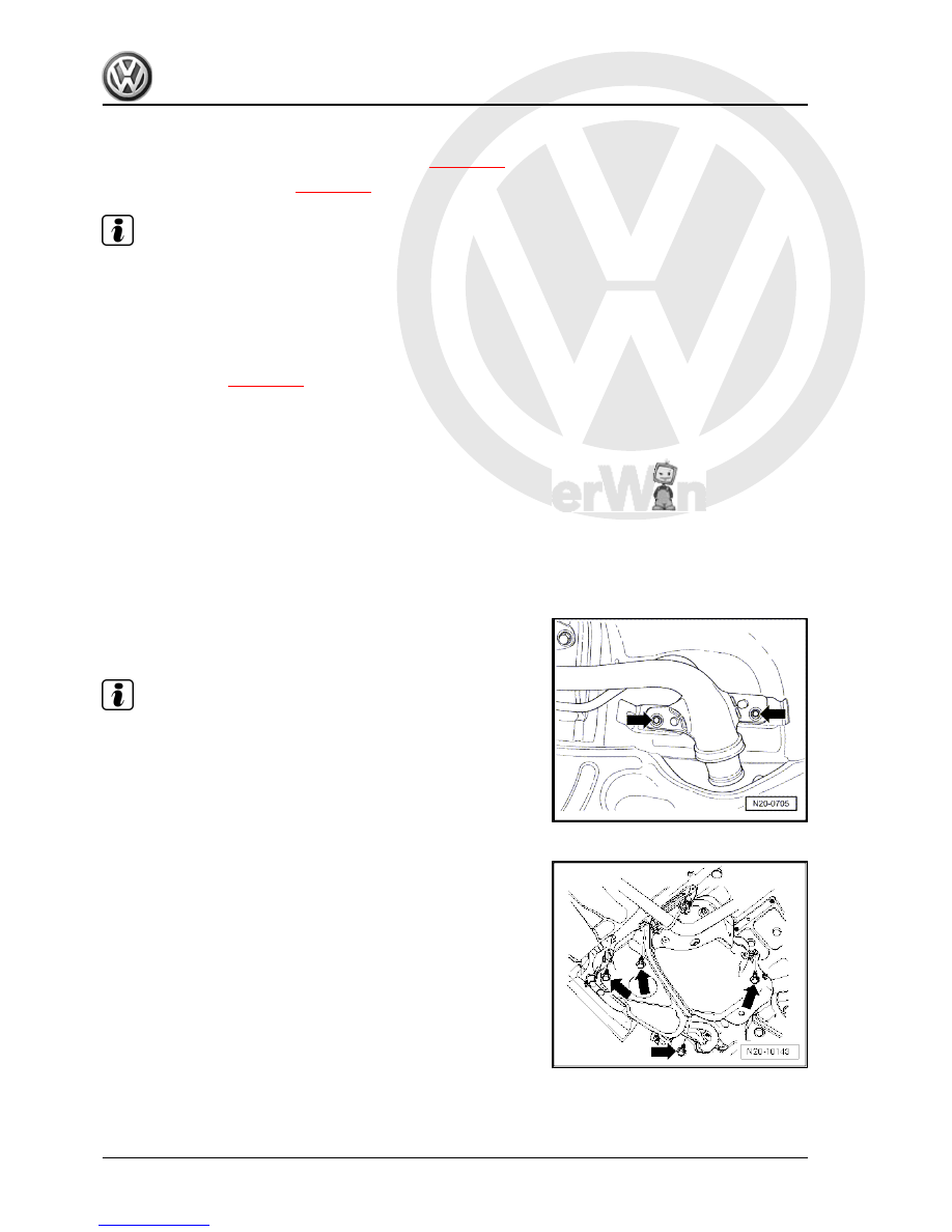
– Remove bolts from filler neck -arrows-.
– Disconnect fuel lines at front right of fuel tank.

Note

Press buttons on hose couplings to do this.

– If vehicle has supplementary heating, separate connector to

metering pump and unclip wire. ⇒  Supplementary heating;

Rep. Gr.  82 ; Removing and installing metering pump -V54

– Support fuel tank using engine and gearbox jack -V.A.G 1383/

A- .

– Remove securing bolts -arrows- for the fuel tank.
– Slowly lower fuel tank.
– Tilt fuel tank to get it past rear axle.

3.3.2

Installing

Installation is carried out in the reverse sequence of removal. In

the process, note the following:

4-cylinder diesel engine (1.9 l engine) - Edition 01.2009

122

     Rep. Gr.20 - Fuel supply system


♦ Clip fuel lines onto fuel tank.

3.4

Removing and installing fuel delivery

unit

Special tools and workshop equipment required
♦ Fuel tank sender unit tool -T10202-

♦ Torque wrench -V.A.G 1332-

3.4.1

Removing

– Note safety precautions before beginning work 

⇒ page 114

 .

Observe rules for cleanliness 

⇒ page 115

 .

– First check whether a coded radio is fitted. If so, obtain anti-

theft coding.

– With the ignition switched off, disconnect battery earth strap.
– The fuel tank must not be more than 

3

/4 full when removing

the suction-jet pump. Drain fuel tank if necessary

⇒ page 117

 .

– Fold rear seats forwards.
– Detach carpet under seats and fold it back. ⇒  General body

repairs, interior; Rep. Gr.  70 ; Load and luggage compartment

trim; Removing and installing luggage compartment floor

– Remove cover from fuel delivery unit.
– Pull connector and fuel lines off flange.

4-cylinder diesel engine (1.9 l engine) - Edition 01.2009

3. Fuel tank, vehicles with front-wheel drive    

123


WARNING

♦ The fuel and the fuel lines in the fuel system can become

very hot (danger of scalding)!

♦ The fuel system is also under pressure! Before opening

the system, place cloths around the connections. Then

carefully loosen connection to release the pressure!

♦ Wear eye and hand protection when performing any type

of repair work on the fuel system!

– Remove union nut using fuel tank sender unit tool -T10202- .
– Pull fuel delivery unit with seal out of opening in fuel tank.

Note

If delivery unit is to be renewed, drain old delivery unit before dis‐

posal.

3.4.2

Installing

– Installing the fuel delivery unit is carried out in reverse order

of removal.

Note

♦

Do not bend fuel gauge sender when installing.

♦

Insert seal for flange or fuel delivery unit dry into opening of

fuel tank.

♦

Moisten seal with fuel only when installing flange or fuel de‐

livery unit.

♦

Ensure that fuel hose connections are tight.

♦

After installing fuel delivery unit, check that the supply, return

and breather lines are still clipped onto the fuel tank.

♦

Note installation position of fuel delivery unit flange: mark on

flange must align with mark on fuel tank.

3.5

Removing and installing fuel gauge

sender

Removing
– Remove fuel delivery unit. 

⇒ page 123

4-cylinder diesel engine (1.9 l engine) - Edition 01.2009

124

     Rep. Gr.20 - Fuel supply system


Installing
– Insert fuel gauge sender into guides on fuel delivery unit and

press upwards until it engages.

3.6

Checking fuel pump

Checking voltage supply of fuel pump -G6- 

⇒ page 125

Checking current consumption of fuel pump -G6- 

⇒ page 126

3.6.1

Checking function and voltage supply

Special tools and workshop equipment required
♦ Hand multimeter -V.A.G 1526 B- or multimeter -V.A.G 1715-

♦ Auxiliary measuring set -V.A.G 1594 C-
♦ Diode test lamp -V.A.G 1527 B-
Test prerequisites
• Fuses must be OK.
• The battery voltage must be at least 11.5 V.
• All electrical consumers, e.g. lights and rear window heating,

must be switched off.

– Fold rear seats forwards.
– Detach carpet under seats and fold it back. ⇒  General body

repairs, interior; Rep. Gr.  70 ; Load and luggage compartment

trim; Removing and installing luggage compartment floor

– Remove cover from fuel delivery unit.
– Switch on ignition. Fuel pump must be heard to run.
– Switch off ignition.
If the fuel pump does not start:
– Pull 4-pin connector off fuel delivery unit flange.

4-cylinder diesel engine (1.9 l engine) - Edition 01.2009

3. Fuel tank, vehicles with front-wheel drive    

125


Content   ..  319  320  321  322   ..