Toyota FJ Cruiser (GSJ 10, 15 series). Manual - part 171


  Index      Toyota     Toyota FJ Cruiser (model GSJ 10, 15 series) - service repair manual 2007 year


Search            


Content   ..  169  170  171  172   ..


Toyota FJ Cruiser (GSJ 10, 15 series). Manual - part 171


EM–116

1GR-FE ENGINE MECHANICAL  –  ENGINE ASSEMBLY

EM

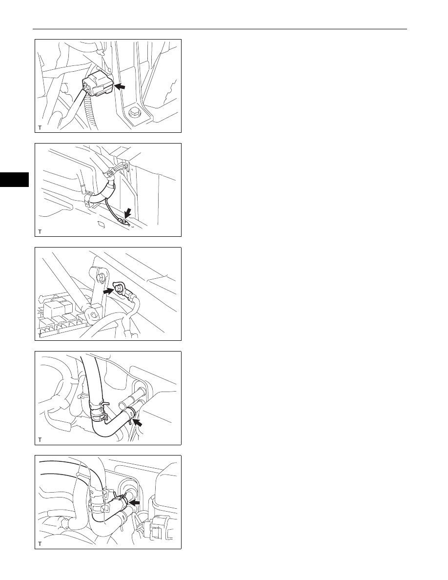
(b) Connect the connector to the engine room relay 

block.

(c) Install the ground wire onto the frame with the bolt.

Torque: 19 N*m (195 kgf*cm, 14 ft.*lbf)

(d) Install the ground wire onto the body with the bolt.

Torque: 8.4 N*m (85 kgf*cm, 7.4 in.*lbf)

23. CONNECT HEATER WATER OUTLET HOSE A (FROM 

HEATER UNIT)

24. CONNECT HEATER INLET WATER HOSE

A126450

A126441

A126442

A126444

A126443

1GR-FE ENGINE MECHANICAL  –  ENGINE ASSEMBLY

EM–117

EM

25. CONNECT NO. 2 FUEL PIPE SUB-ASSEMBLY

(a) Connect the No. 2 fuel tube connector and fuel pipe, 

and install the No. 2 fuel pipe clamp.  
NOTICE:
Align the fuel tube connector with the pipe, then 
push the fuel tube connector in until the retainer 
makes a click sound. If the connection is tight, 
apply a small amount of engine oil to the tip of 
the pipe. After connecting, pull the pipe and 
connector to make sure that they are securely 
connected.

26. CONNECT NO. 1 FUEL PIPE SUB-ASSEMBLY

(a) Connect the No. 1 fuel tube connector and fuel pipe, 

and install the No. 2 fuel pipe clamp.  
NOTICE:
Align the fuel tube connector with the pipe, then 
push the fuel tube connector in until the retainer 
makes a click sound. If the connection is tight, 
apply a small amount of engine oil to the tip of 
the pipe. After connecting, pull the pipe and 
connector to make sure that they are securely 
connected.

27. INSTALL VANE PUMP ASSEMBLY (See page 

PS-14

)

28. INSTALL COOLER COMPRESSOR ASSEMBLY (See 

page 

ES-421

)

29. INSTALL GENERATOR ASSEMBLY (See page 

CH-17

)

30. INSTALL INTAKE AIR SURGE TANK (See page 

FU-

17

)

31. INSTALL NO. 2 SURGE TANK STAY (See page 

FU-19

)

32. INSTALL NO. 1 SURGE TANK STAY (See page 

FU-19

)

33. INSTALL OIL BAFFLE PLATE (See page 

FU-19

)

34. INSTALL THROTTLE BODY BRACKET (See page 

FU-

19

)

35. INSTALL FLYWHEEL SUB-ASSEMBLY (for Manual 

Transmission)
(a) Using SST, hold the crankshaft.

SST

09213-54015 (91651-60855), 09330-00021

A126503

A126502

A076326

EM–118

1GR-FE ENGINE MECHANICAL  –  ENGINE ASSEMBLY

EM

(b) Apply adhesive to the 2 or 3 end threads of the 

bolts. 
Adhesive:

Toyota Genuine Adhesive 1324, Three Bond 
1324 or the equivalent.

(c) Install the flywheel and 2 spacers onto the 

crankshaft.

(d) Install the flywheel with the 6 bolts in the order 

shown in the illustration.
Torque: 83 N*m (846 kgf*cm, 61 ft.*lbf)

36. INSTALL DRIVE PLATE AND RING GEAR SUB-

ASSEMBLY (for Automatic Transmission)
(a) Using SST, hold the crankshaft.

SST

09213-54015 (91651-60855), 09330-00021

(b) Apply adhesive to the 2 or 3 end threads of the 

bolts. 
Adhesive:

Toyota Genuine Adhesive 1324, Three Bond 
1324 or the equivalent.

(c) Install the drive plate and 2 spacers onto the 

crankshaft.

(d) Install the drive plate with the 6 bolts in the order 

shown in the illustration.
Torque: 83 N*m (846 kgf*cm, 61 ft.*lbf)

37. INSTALL CLUTCH DISC ASSEMBLY (for Manual 

Transmission)
Refer to the procedures up to "INSTALL CLUTCH DISC 
ASSEMBLY" (See page 

CL-23

).

A057108

1

2

3

4

5

6

7

8

G036171E01

A076326

A057108

1

2

3

4

5

6

7

8

A076327E02

1GR-FE ENGINE MECHANICAL  –  ENGINE ASSEMBLY

EM–119

EM

38. INSTALL MANUAL TRANSMISSION UNIT ASSEMBLY 

(for Manual Transmission)
Refer to the procedures up to "INSTALL MANUAL 
TRANSMISSION" (See page 

MT-11

).

39. INSTALL AUTOMATIC TRANSMISSION ASSEMBLY 

(for Automatic Transmission)
Refer to the procedures up to "INSTALL AUTOMATIC 
TRANSMISSION" (See page 

AT-175

 or 

AT-181

).

40. INSTALL RADIATOR ASSEMBLY

Refer to the procedures up to "INSTALL RADIATOR 
ASSEMBLY" (See page 

CO-28

).

41. INSTALL HOOD SUB-ASSEMBLY

(a) Install the hood with the 4 bolts.
(b) Connect the windshield washer hose.

42. INSTALL HOOD SUPPORT (See page 

ED-5

)

43. INSTALL BATTERY

44. ADD ENGINE COOLANT (See page 

CO-3

)

45. ADD ENGINE OIL (See page 

LU-5

)

46. PERFORM INITIALIZATION (for Automatic 

Transmission)
(See page 

AT-19

 or 

AT-19

47. CHECK FOR ENGINE COOLANT LEAKAGE (See 

page 

CO-4

)

48. CHECK FOR ENGINE OIL LEAKAGE

49. CHECK FOR FUEL LEAKAGE

50. CHECK FOR EXHAUST GAS LEAKAGE

51. INSPECT IGNITION TIMING (See page 

EM-1

)

52. INSPECT ENGINE IDLING SPEED (See page 

EM-2

)

53. INSPECT COMPRESSION (See page 

EM-3

)

54. INSPECT CO/HC (See page 

EM-3

)

55. INSPECT AND ADJUST FRONT WHEEL ALIGNMENT

Refer to the procedures up to "INSPECT AND ADJUST 
FRONT WHEEL ALIGNMENT" (See page 

SP-2

).

A126452


Content   ..  169  170  171  172   ..