Toyota FJ Cruiser (GSJ 10, 15 series). Manual - part 74


  Index      Toyota     Toyota FJ Cruiser (model GSJ 10, 15 series) - service repair manual 2007 year


Search            


Content   ..  72  73  74  75   ..


Toyota FJ Cruiser (GSJ 10, 15 series). Manual - part 74


1GR-FE ENGINE CONTROL SYSTEM  –  SFI SYSTEM

ES–251

ES

OK

(a) Shift the transmission gear selector lever to the neutral 

position.

(b) Jack up the vehicle.
(c) Turn the ignition switch ON.
(d) Check the voltage between the terminals of the B3 and 

E46 ECM connectors as the wheel is turned slowly.
Standard

HINT:
The output voltage should fluctuate up and down 
similarly to the diagram on the left when the wheel is 
turned slowly.

NG

OK

2

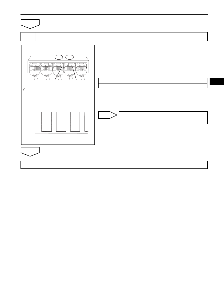
INSPECT ECM (SPD VOLTAGE)

ECM Connector

B3

E46

E1 (-)

SPD (+)

12 V

0 V

Turn Wheel

A116298E02

Tester Connections

Specified Conditions

SPD (E46-8) - E1 (B3-1)

Voltage generated intermittently

REPAIR OR REPLACE HARNESS OR 
CONNECTOR

REPLACE ECM (See page 

ES-446

)

ES–252

1GR-FE ENGINE CONTROL SYSTEM  –  SFI SYSTEM

ES

DESCRIPTION

The stop light switch is a duplex system that transmits two signals: STP and ST1-. These two signals are 
used by the ECM to monitor whether or not the brake system is working properly. If the signals, which 
indicate the brake pedal is being depressed and released, are detected simultaneously, the ECM 
interprets this as a malfunction in the stop light switch and sets the DTC.
HINT:
The normal conditions are as shown in the table below. The signals can be read using an intelligent tester.

DTC

P0504

Brake Switch "A" / "B" Correlation

Signals

Brake Pedal Released

In Transition

Brake Pedal Depressed

STP

OFF

ON

ON

ST1-

ON

ON

OFF

DTC No.

DTC Detection Conditions

Trouble Areas

P0504

Conditions (a), (b) and (c) continue for 0.5 seconds or more (1 
trip detection logic)
(a) Ignition switch ON
(b) Brake pedal released
(c) STP signal OFF when ST1- signal OFF

Short in stop light switch signal circuit

STOP  fuse

Stop light switch

ECM

1GR-FE ENGINE CONTROL SYSTEM  –  SFI SYSTEM

ES–253

ES

WIRING DIAGRAM

INSPECTION PROCEDURE

HINT:
Read freeze frame data using an intelligent tester. Freeze frame data record the engine condition when 
malfunctions are detected. When troubleshooting, freeze frame data can help determine if the vehicle was 
moving or stationary, if the engine was warmed up or not, if the air-fuel ratio was lean or rich, and other 
data, from the time the malfunction occurred.

1

2

High Mounted 
Stop Light

Stop

Stop

STOP

ALT

Battery

IGN

IG1

Stop Light Switch

Skid Control ECU

STOP LP CTRL

ECM

ST1-

STP

Rear Combination  
Light (RH)

Rear Combination  
Light (LH)

1

2

1

3

1

3

T1

L14

L11

15

E47

16

E47

STP0 A4

5

1

3

2

4

3

2

4

1

A3

16

A133421E01

ES–254

1GR-FE ENGINE CONTROL SYSTEM  –  SFI SYSTEM

ES

(a) Check whether the stop lights turn on and off normally 

when the brake pedal is depressed and released.
OK:

Stop lights turn ON when brake pedal is depressed.

NG

OK

(a) Remove the stop light switch assembly.
(b) Check the resistance.

Standard Resistance

(c) Reinstall the stop light switch assembly.

NG

OK

(a) Connect an intelligent tester to the DLC3.
(b) Turn the ignition switch ON and turn the tester ON.
(c) Select the following menu items: DIAGNOSIS / 

ENHANCED OBD II / DATA LIST / PRIMARY / STOP 
LIGHT SW.

(d) Check the STP signal when the brake pedal is 

depressed and released.
Standard

(e) Measure the voltage between the terminals of the B3 

and E47 ECM connectors.
Standard Voltage

OK

1

CHECK OPERATION OF STOP LIGHT

REPAIR OR REPLACE STOP LIGHT SWITCH 
CIRCUIT

2

INSPECT STOP LIGHT SWITCH ASSEMBLY

Free

Pushed in

1

2

4

3

A072924E09

Switch Positions 

Tester Connections

 Specified Conditions

Switch pin free

1 - 2

Below 1 

3 - 4

10 k

 or higher

Switch pin pushed in

1 - 2

10 k

 or higher

3 - 4

Below 1 

REPLACE STOP LIGHT SWITCH ASSEMBLY

3

READ VALUE USING INTELLIGENT TESTER (STP SIGNAL AND ST1- VOLTAGE)

ECM Connector

E1(-)

ST1-(+)

Brake Pedal 
Released

Brake Pedal 
Depressed

E47

B3

G035663E04

Brake Pedal Operations

Specified Conditions

Depressed

STP signal ON

Released

STP signal OFF

Tester Connections

Brake Pedal Operations

Specified Conditions

ST1- (E47-16) - E1 (B3-

1)

Depressed

Below 1.5 V

Released

7.5 to 14 V

CHECK FOR INTERMITTENT PROBLEMS


Content   ..  72  73  74  75   ..