Toyota Corolla (2004+). Manual - part 69

05-256
DIAGNOSTICS
- SFI SYSTEM (April, 2003)
4
PERFORM ACTIVE TEST USING HAND-HELD TESTER(CHECK IAC VALVE
OPERATION)
(a) Warm up the engine to the normal operating temperature.
(b) Switch off all the accessories.
(c)
Switch off the A/C.
(d) Shift the lever into the neutral position.
(e) Connect the hand-held tester to the DLC3.
(f)
Select the item ”DIAGNOSIS / ENHANCED OBD II / ACTIVE TEST / ISC DUTY RATIO”.
(g) Check that the engine RPM varies when changing the ISC duty ratio.
Engine RPM:
Engine RPM fluctuates up and down in response to the ISC duty ratio variation.
OK CHECK FOR INTERMITTENT PROBLEMS
(See page 05-41)
NG
5
CHECK A/C SIGNAL CIRCUIT
NG REPAIR OR REPLACE
OK
6
CHECK BLOCKAGE OF IAC VALVE AND PASSAGE TO BYPASS THROTTLE
VALVE
NG REPLACE IDLE AIR CONTROL VALVE
OK
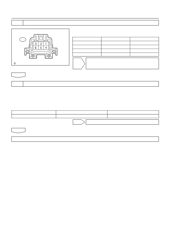
7
CHECK HARNESS AND CONNECTOR
(a) Disconnect the I1 IAC valve connector.
Wire Harness Side:
(b) Turn the ignition switch ON.
ISC valve Connector
(c)
Measure the voltage between the terminals of the IAC
I1
valve wire harness side connector.
Standard:
1
2
3
Tester Connection
Specified Condition
VISC (+)
VISC (I1-2) - GND (I1-3)
9 to 14 V
Front View
(d) Reconnect the IAC valve connector.
GND (-)
A66264
NG REPAIR OR REPLACE HARNESS OR
CONNECTOR
OK

05-257
DIAGNOSTICS
- SFI SYSTEM (April, 2003)
8
CHECK HARNESS AND CONNECTOR(IAC VALVE - ECM)
(a) Disconnect the I1 IAC valve connector.
(b) Disconnect the E3 ECM connector.
E3
(c)
Check the resistance between the wire harness side con-
nectors.
Standard (Check for open):
Tester Connection
Specified Condition
RSO
DUTY (I1-1) - RSO (E3-5)
Below 1 W
E01
GND (I1-3) - E01 (E3-7)
ECM Connector
A65743
Standard (Check for short):
Tester Connection
Specified Condition
Wire Harness Side:
DUTY (I1-1) or RSO (E3-5) - Body ground
10 kW or higher
ISC valve Connector
(d) Reconnect the ECM connector.
(e) Reconnect the IAC valve connector.
I1
1
2
3
DUTY
GND
Front View
A66264
NG REPAIR OR REPLACE HARNESS OR
CONNECTOR
OK
9
INSPECT IDLE AIR CONTROL VALVE (See page 10-1)
NG REPLACE IDLE AIR CONTROL VALVE
OK
REPLACE ECM (See page 10-11)
OBD II scan tool (excluding hand-held tester):
1
CHECK OTHER DTC OUTPUT
(a) Connect the hand-held tester to the DLC3.
Result:
Display (DTC output)
Proceed to
P0505
A
”P0511” and other DTCs
B
B
Go to step 6
A

05-258
DIAGNOSTICS
- SFI SYSTEM (April, 2003)
2
CHECK CONNECTION OF PCV HOSE
NG REPAIR OR REPLACE PCV HOSE
OK
3
CHECK AIR INDUCTION SYSTEM
NG REPAIR OR REPLACE
OK
4
CHECK A/C SIGNAL CIRCUIT
NG REPAIR OR REPLACE
OK
5
CHECK BLOCKAGE OF IAC VALVE AND PASSAGE TO BYPASS THROTTLE
VALVE
NG REPAIR OR REPLACE IDLE AIR CONTROL
VALVE
OK
6
CHECK HARNESS AND CONNECTOR
(a) Disconnect the I1 IAC valve connector.
Wire Harness Side:
(b) Turn the ignition switch ON.
ISC valve Connector
(c)
Measure the voltage between the terminals of the IAC
I1
valve wire harness side connector.
Standard:
1
2
3
Tester Connection
Specified Condition
VISC (+)
VISC (I1-2) - GND (I1-3)
9 to 14 V
Front View
(d) Reconnect the IAC valve connector.
GND (-)
A66264
NG REPAIR OR REPLACE HARNESS OR
CONNECTOR
OK

05-259
DIAGNOSTICS
- SFI SYSTEM (April, 2003)
7
CHECK HARNESS AND CONNECTOR(IAC VALVE - ECM)
(a) Disconnect the I1 IAC valve connector.
(b) Disconnect the E3 ECM connector.
E3
(c)
Check the resistance between the wire harness side con-
nectors.
Standard (Check for open):
Tester Connection
Specified Condition
RSO
DUTY (I1-1) - RSO (E3-5)
Below 1 W
E01
GND (I1-3) - E01 (E3-7)
ECM Connector
A65743
Standard (Check for short):
Tester Connection
Specified Condition
Wire Harness Side:
DUTY (I1-1) or RSO (E3-5) - Body ground
10 kW or higher
ISC valve Connector
(d) Reconnect the ECM connector.
(e) Reconnect the IAC valve connector.
I1
1
2
3
DUTY
GND
Front View
NG REPAIR OR REPLACE HARNESS OR
A66264
CONNECTOR
OK
8
INSPECT IDLE AIR CONTROL VALVE (See page 10-1)
NG REPAIR OR REPLACE IDLE AIR CONTROL
VALVE
OK
REPLACE ECM(See page 10-11)

05-260
DIAGNOSTICS
- SFI SYSTEM (April, 2003)
059UV-08
DTC
P0560
SYSTEM VOLTAGE
MONITOR DESCRIPTION
The battery supplies electricity to the ECM even when the ignition switch is OFF. This electricity allows the
ECM store data such as DTC history, freeze frame data, fuel trim values, and other data. If the battery voltage
falls below a minimum level, the ECM will conclude that there is a fault in the power supply circuit. At the next
engine start, the ECM will turn on the MIL and a DTC will be set.
DTC No.
DTC Detection Condition
Trouble Area
F Open in back-up power source circuit
P0560
Open in back-up power source circuit
F ECM
MONITOR STRATEGY
Related DTCs
P0560
System voltage malfunction
Required sensors/components
ECM
Frequency of operation
Continuous
Duration
3 seconds
MIL operation
Immediately (*1)
Sequence of operation
None
*1: The DTC is set immediately. The MIL will be illuminated after the next engine start.
TYPICAL ENABLING CONDITIONS
Specification
Item
Minimum
Maximum
The monitor will run whenever the follow-
See ”List of Disable a Monitor” (On page 05-25)
ing DTCs are not present
Stand-by RAM
Initialized
TYPICAL MALFUNCTION THRESHOLDS
Detection Criteria
Threshold
Battery voltage
Less than 3.5 V

05-261
DIAGNOSTICS
- SFI SYSTEM (April, 2003)
WIRING DIAGRAM
Engine Room R/B and J/B
ECM
1
EFI
1
3
BATT
1
2
R-W
R-W
1A
1
IA2
E6
B
7
BR
E4
E1
A
FL MAIN
J4 J/C
A
BR
Battery
EB
A84933
INSPECTION PROCEDURE
HINT:
Read freeze frame data using the hand−held tester or the OBD II scan tool. Freeze frame data records the
engine conditions when a malfunction is detected. When troubleshooting, it is useful for determining whether
the vehicle was running or stopped, the engine was warmed up or not, the air-fuel ratio was lean or rich,
etc. at the time of the malfunction.

05-262
DIAGNOSTICS
- SFI SYSTEM (April, 2003)
1
CHECK FUSE(EFI FUSE)
(a) Remove the EFI fuse from the engine room R/B.
Engine Room R/B:
(b) Check for continuity in the EFI fuse.
Standard: Continuity
(c)
Reinstall the EFI fuse.
EFI fuse
A65754
NG CHECK FOR SHORT IN ALL HARNESSES AND
COMPONENTS CONNECTED FUSE
OK
2
INSPECT ECM(BATT VOLTAGE)
(a) Measure the voltage between the terminals of the E4 and
E6 ECM connectors.
E4
E6
Standard:
Tester Connection
Specified Condition
BATT (E6-3) - E1 (E4-7)
8 to 14 V
E1 (-)
BATT (+)
ECM Connector
A65741
OK REPLACE ECM (See page 10-11)
NG

05-263
DIAGNOSTICS
- SFI SYSTEM (April, 2003)
3
CHECK HARNESS AND CONNECTOR(ECM - EFI FUSE, EFI FUSE - BATTERY)
(a)
Check the harness and the connector between the EFI
fuse and ECM.
E6
(1)
Remove the EFI fuse from the engine room R/B.
(2)
Disconnect the E6 ECM connector.
(3)
Check the resistance between the wire harness
side connectors.
Standard (Check for open):
BATT
Tester Connection
Specified Condition
ECM Connector
A65748
EFI fuse (2) - BATT (E6-3)
Below 1 W
Standard (Check for short):
Engine Room R/B:
Tester Connection
Specified Condition
EFI fuse (2) or BATT (E6-3) - Body ground
10 kW or higher
(4)
Reconnect the ECM connector.
(5)
Reinstall the EFI fuse.
(b)
Check the harness and the connector between the EFI
fuse and battery.
2
EFI fuse
(1)
Remove the EFI fuse from the engine room R/B.
1
(2)
Disconnect the battery positive terminal.
A65756
(3)
Check the resistance between the wire harness
side connectors.
Standard (Check for open):
Tester Connection
Specified Condition
Battery positive terminal - EFI fuse (1)
Below 1 W
Standard (Check for short):
Tester Connection
Specified Condition
Battery positive terminal or EFI fuse (1) - Body ground
10 kW or higher
(4)
Reconnect the battery positive terminal.
(5)
Reinstall the EFI fuse.
NG REPAIR OR REPLACE HARNESS OR
CONNECTOR
OK
CHECK AND REPLACE ENGINE ROOM RELAY BLOCK ASSY

05-264
DIAGNOSTICS
- SFI SYSTEM (April, 2003)
052O7-10
DTC
P0606
ECM/PCM PROCESSOR
MONITOR DESCRIPTION
The ECM continuously monitors its internal circuits. This self-check insures that the ECM is functioning prop-
erly. If a malfunction is detected, the ECM will set the appropriate DTC and illuminate the MIL.
The two CPUs, main and sub CPU inside the ECM, perform continuous mutual monitoring. If there is differ-
ence between outputs from the two CPUs that deviates from standard level ranges, the ECM concludes that
there is a fault and sets a DTC.
DTC No.
DTC Detection Condition
Trouble Area
P0606
ECM internal error
F ECM
MONITOR STRATEGY
Related DTCs
P0606
ECM range check/description
Required sensors/components
ECM
Frequency of operation
Continuous
Duration
1 seconds
MIL operation
Immediately
Sequence of operation
None
TYPICAL ENABLING CONDITIONS
Specification
Item
Minimum
Maximum
The monitor will run whenever the follow-
See ”List of Disable a Monitor” (On page 05-25)
ing DTCs are not present
TYPICAL MALFUNCTION THRESHOLDS
Detection Criteria
Threshold
ECM error
INSPECTION PROCEDURE
HINT:
Read freeze frame data using the hand−held tester or the OBD II scan tool. Freeze frame data records the
engine conditions when a malfunction is detected. When troubleshooting, it is useful for determining whether
the vehicle was running or stopped, the engine was warmed up or not, the air-fuel ratio was lean or rich,
etc. at the time of the malfunction.
REPLACE ECM (See Page 10-11)

05-265
DIAGNOSTICS
-
SFI SYSTEM (April, 2003)
05CRX-02
DTC
P0617
STARTER RELAY CIRCUIT HIGH
MONITOR DESCRIPTION
While the engine is being cranked, the battery positive voltage is applied to terminal STA of the ECM.
If the ECM detects the starter control signal (STA) while the vehicle is driving, it will conclude that there is
a fault in the starter control circuit. The ECM will turn on the MIL and a DTC is set.
DTC No.
DTC Detection Condition
Trouble Area
When all conditions (a), (b) and (c) are satisfied with battery
F Short in Park/Neutral position switch circuit (A/T)
(+B) voltage 10.5 V or more for 20 seconds
F Park/Neutral position switch (A/T)
P0617
(a) Vehicle speed greater than 12 mph (20 km/h)
F Clutch start switch (M/T)
(b) Engine revolution greater than 1,000 rpm
F ECM
(c) STA signal ON
MONITOR STRATEGY
Related DTCs
P0617
Starter signal error
Main sensors
Starter signal
Required sensors/components
Related sensors
Vehicle speed sensor, engine speed sensor
Frequency of operation
Continuous
Duration
20 seconds
MIL operation
Immediately
Sequence of operation
None
TYPICAL ENABLING CONDITIONS
Specification
Item
Minimum
Maximum
The monitor will run whenever the follow-
See ”List of Disable a Monitor” (On page 05-25)
ing DTCs are not present
Battery voltage
10.5 V
-
Vehicle speed
12.4 mph (20 km/h)
-
Engine speed
1,000 rpm
-
TYPICAL MALFUNCTION THRESHOLDS
Detection Criteria
Threshold
Starer signal
ON (at more than 12.4 mph (20 km/h) and more than 1,000 rpm)

05-266
DIAGNOSTICS
- SFI SYSTEM (April, 2003)
WIRING DIAGRAM
ECM
8
R(*2)
E4
NSW
A2
Park/Neutral
9
J3
E
STA
E4
Position Switch
Junction
A
9
6
J2
Connector
R(*2)
J2
A
I10
R(*2)
Ignition
Switch
12
5
4
R
R(*2)
II2
AM2 ST2
R(*1)
B
Instrument Panel J/B
IA2
3
6
IM
B(*2)
B
R(*1)
3
2
ST
1
AM2
C8
Relay
Clutch
5
1
Start
Switch
3
IM
1
IM IL
11
4
IF
2
B-R
From Terminal 21
B
of TVIP ECU
B(*1)
IA4 2
B-W
B-R(*3)
(*3)
B(*2)
B-R
3
1
W-B
S8
G
G
1
Starter
J2
J2
II1
7
IA5 10
II2
11
MAIN
2
Cut
4
2
Relay
B(*1, *4)
Engine
J2
G
B
Room
B(*3)
Junction
1
B
R/B and
B(*3)
Connector
(*1,*3)
1
1A
B(*3)
J/B
B(*1)
B(*2)
B
FL
B(*4)
B(*4)
MAIN
1
S3
1
S2
B-R
A
J6
*1: M/T
J/C
Battery
*2: A/T
*3: W/TVIP System
IE
*4: W/O TVIP System
A84934

05-267
DIAGNOSTICS
-
SFI SYSTEM (April, 2003)
INSPECTION PROCEDURE
HINT:
F
This DTC chart is on the premise that the engine is cranked normally. If the engine is not cranked, pro-
ceed to the problem symptoms table on page 05-42.
F
Read freeze frame data using the hand−held tester or the OBD II scan tool. Freeze frame data records
the engine conditions when a malfunction is detected. When troubleshooting, it is useful for determin-
ing whether the vehicle was running or stopped, the engine was warmed up or not, the air-fuel ratio
was lean or rich, etc. at the time of the malfunction.
Hand-held tester:
1
READ VALUE OF HAND-HELD TESTER(STARTER SIGNAL)
(a) Connect the hand-held tester or OBD II scan tool to the DLC3.
(b) Turn the ignition switch ON and push the hand-held tester main switch ON.
(c)
Select the item ”DIAGNOSIS / ENHANCED OBD II / DATA LIST / ALL / STARTER SIG” and read the
value displayed the hand-held tester.
Result:
Ignition switch position
ON
START
STA Signal
OFF
ON
OK REPLACE ECM (See page 10-11)
NG

05-268
DIAGNOSTICS
- SFI SYSTEM (April, 2003)
2
INSPECT PARK/NEUTRAL POSITION SWITCH OR CLUTCH START SWITCH
Component Side:
(a) Inspect the park/neutral position switch. (A/T)
Park/Neutral Position Switch
(1)
Disconnect the A2 park/neutral position switch con-
A2
nector.
(2)
Check for continuity between each terminal shown
below when the shift lever is moved to each range.
Standard:
Shift Range
Tester Connection
Specified Condition
P
1 - 3, 6 - 9
Front View
A79133
R
2 - 3
N
3 - 5, 6 - 9
Continuity
D
3 - 7
2
3 - 4
L
3 - 8
(3)
Reconnect the park/neutral position switch con-
nector.
(b) Inspect the clutch start switch. (M/T)
8.0
0.5 mm (0.315
0.020 in)
(1)
Disconnect the C8 clutch start switch connector.
C8
(2)
Check for continuity between terminals when the
switch ON and OFF.
2
Standard:
Switch Position
Terminal
Specified Condition
1
ON (pushed)
Continuity
1- 2
ON OFF
OFF (free)
No continuity
A82259
(3)
Reconnect the clutch start switch connector.
NG REPLACE PARK/NEUTRAL POSITION SWITCH
OR CLUTCH START SWITCH (GO TO NEXT
STEP 3 AFTER THE REPLACEMENT)
OK
3
READ VALUE OF HAND-HELD TESTER(STARTER SIGNAL)
(a) Connect the hand-held tester to or OBD II scan tool the DLC3.
(b) Turn the ignition switch ON and push the hand-held tester main switch ON.
(c)
Select the item ”DIAGNOSIS / ENHANCED OBD II / DATA LIST / ALL / STARTER SIG” and read its
value displayed the hand-held tester.
Result:
Ignition Switch Position
ON
START
STA Signal
OFF
ON
OK SYSTEM OK
NG
05-269
DIAGNOSTICS
- SFI SYSTEM (April, 2003)
4
INSPECT IGNITION OR STARTER SWITCH ASSY
(a) Check for continuity between the connector terminals
Component Side:
Ignition Switch
shown in the chart below.
I10
Switch Position
Tester Connection
Specified Condition
LOCK
All Terminals
No continuity
ACC
1-3
Continuity
ON
1-2, 1-3, 2-3, 5-6
Continuity
START
1-2, 4-5, 4-6, 5-6
Continuity
NG REPLACE IGNITION OR STARTER SWITCH
Front View
B50489
ASSY (GO TO NEXT STEP 5 AFTER THE RE-
PLACEMENT
OK
5
READ VALUE OF HAND-HELD TESTER(STARTER SIGNAL)
(a) Connect the hand-held tester or OBD II scan tool to the DLC3.
(b) Turn the ignition switch ON and push the hand-held tester main switch ON.
(c)
Select the item ”DIAGNOSIS / ENHANCED OBD II / DATA LIST / ALL / STARTER SIG” and read its
value displayed the hand-held tester.
Result:
Ignition Switch Position
ON
START
STA Signal
OFF
ON
OK SYSTEM OK
NG
REPAIR OR REPLACE HARNESS AND CONNECTOR

05-270
DIAGNOSTICS
- SFI SYSTEM (April, 2003)
OBD II scan tool (excluding hand-held tester):
1
INSPECT ECM
(a) Turn the ignition switch ON.
(b) Measure the voltage between the terminals of the E4
E4
ECM connector.
Standard:
Tester Connection
Specified Condition
STA (E4-9) - E1 (E4-7)
0 V
(c)
Measure the voltage between the terminals of the E4
E1(-)
STA(+)
ECM connector when the engine is cranked.
ECM Connector
A18294
Standard:
Tester Connection
Specified Condition
STA (E4-9) - E1 (E4-7)
5.5 V or more
OK REPLACE ECM (See page 10-11)
NG