Toyota Corolla (2004+). Manual - part 44

DIAGNOSTICS
- ELECTRONIC CONTROLLED AUTOMATIC
05-351
TRANSAXLE [ECT] (April, 2003)
05DTQ-01
DIAGNOSIS SYSTEM
(a) Description
(1)
When troubleshooting OBD II vehicles, the only dif-
ference from the usual troubleshooting procedure
is that you need to connect an OBD II scan tool com-
plying with SAE J1987 or a hand-held tester to the
vehicle, and read off various data output from the
vehicle’s ECM.
(2)
OBD II regulations require that the vehicle’s on-
board computer illuminate the Malfunction Indicator
Lamp (MIL) on the instrument panel when the com-
puter detects a malfunction in the computer itself or
in the drive system components which affect the ve-
hicle emissions. In addition to the MIL illuminating
when a malfunction is detected, the applicable
DTCs prescribed by SAE J2012 are recorded in the
FI0534
ECM memory (See page 05-372).
If the malfunction does not occur in 3 consecutive trips, the MIL
goes off but the DTCs remain in the ECM memory.
(3)
To check the DTCs, connect the OBD II scan tool or
hand-held tester to the DLC3 of the vehicle. The
OBD II scan tool or hand-held tester also enables
you to erase the DTCs and check freeze frame data
and various forms of engine data (For manual
book).
(4)
The DTCs include SAE controlled codes and
Manufacturer controlled codes. SAE controlled
codes must be set as prescribed by the SAE, while
Manufacturer controlled codes can be set freely by
a manufacturer within the prescribed limits (See the
DTC chart on page 05-372).
(5)
The diagnosis system operates in the normal mode
during the normal vehicle use, and also has a check
mode for technicians to simulate malfunction symp-
toms and perform troubleshooting. Most DTCs use
2 trip detection logic(*) to prevent erroneous detec-
tion. By switching the ECM to the check mode when
troubleshooting, the technician can cause the MIL
to illuminate for a malfunction that is only detected
once or momentarily. (hand-held tester).
(6)
*2 trip detection logic:
When a malfunction is first detected, the malfunc-
tion is temporarily stored in the ECM memory. If the
same malfunction is detected again during the se-
cond test drive, this second detection causes the
MIL to illuminate.

05-352
DIAGNOSTICS
- ELECTRONIC CONTROLLED AUTOMATIC
TRANSAXLE [ECT] (April, 2003)
(b) Inspect the DLC3.
D1
The vehicle’s ECM uses ISO 9141-2 for communication.
The terminal arrangement of DLC3 complies with SAE
1 2
3
45678
J1962 and matches the ISO 9141-2 format.
9 10111213141516
DLC3
A04550
Tester connection
Condition
Specified condition
7 (Bus Line) - 5 (Signal ground)
During communication
Pulse generation
4 (Chassis Ground) - Body
Always
1 W or less
5 (Signal Ground) - Body
Always
1 W or less
16 (B+) - Body
Always
9 to 14 V
HINT:
If your display shows UNABLE TO CONNECT TO VEHICLE
when you have connected the cable of the OBD II scan tool or
hand-held tester to the DLC3, turned the ignition switch to the
ON position and operated the scan tool, there is a problem on
the vehicle side or tool side.
F
If the communication is normal when the tool is connected
to another vehicle, inspect the DLC3 on the original ve-
hicle.
F
If the communication is still impossible when the tool is
connected to another vehicle, the problem is probably in
the tool itself, so consult the Service Department listed in
the tool’s manual instruction.
(c)
Measure the battery voltage.
Battery Voltage: 11 to 14 V
If voltage is below 11 V, recharge the battery before proceeding.
(d) Check the MIL.
(1)
The MIL comes on when the ignition switch is turned
to the ON position and the engine is not running.
HINT:
If the MIL does not light up, troubleshoot the combination meter.
(2)
When the engine is started, the MIL should go off.
If the lamp remains on, it means that the diagnosis
system has detected a malfunction or abnormality
in the system.

DIAGNOSTICS
- ELECTRONIC CONTROLLED AUTOMATIC
05-353
TRANSAXLE [ECT] (April, 2003)
05DTR-01
DTC CHECK/CLEAR
1.
DTC CHECK (NORMAL MODE)
NOTICE:
Hand-held tester only:
When the diagnostic system is switched from the normal
mode to the check mode, all the DTCs and freeze frame
data r ecorded in the normal mode will be erased. So before
switching modes, always check the DTCs and freeze frame
data, and note them down.
Hand-Held Tester
(a) Checking DTCs using the OBD II scan tool or hand-held
tester.
(1)
Turn the ignition switch off.
(2)
Connect the OBD II scan tool or hand-held tester
to DLC3.
(3)
Turn the ignition switch to the ON position.
(4)
Use the OBD II scan tool or hand-held tester to
check the DTCs and freeze frame data and note
DLC3
G23391
them down (For operating manuals, see the
OBD II scan tool’s manual book).
(5)
See page 05-372 to confirm the details of the
DTCs.
NOTICE:
When simulating symptoms with an OBD II scan tool (ex-
cluding hand-held tester) to check the DTCs, use the nor-
mal mode. For codes on the DTCs chart subject to ”2 trip
detection log ic”, turn the ignition switch off after the symp-
tom is simulated once. Then repeat the simulation process
again. When the problem has been simulated twice, the MIL
is indicated on the instrument panel and DTCs are re-
corded in the ECM.
2.
DTC CLEAR
(a) When using the OBD II scan tool or hand-held tester:
Clearing the DTCs.
(1)
Connect the OBD II scan tool or hand-held tester
to the DLC3.
(2)
Turn the ignition switch to the ON position.
(3)
When operating the OBD II scan tool (complying
with SAE J1978) or hand-held tester to erase the
codes, the DTCs and freeze frame data will be
erased. (See the OBD II scan tool’s manual book
for operating manuals.)
(b) When not using the OBD II scan tool or hand-held tester:
Clearing the DTCs.
(1)
Disconnecting the battery terminal or remove the
EFI and ETCS fuses from the engine room J/B for
60 seconds or more.

05-372
DIAGNOSTICS
- ELECTRONIC CONTROLLED AUTOMATIC
TRANSAXLE [ECT] (April, 2003)
0527K-19
DIAGNOSTIC TROUBLE CODE CHART
If a DTC is displayed during the DTC check, check the circuit listed in the table below and proceed to the
page given.
* : F ... MIL light up
DTC No.
Detection Item
Trouble Area
MIL *
Memory
(See Page)
_ Combination meter
P0500
_ Open or short in vehicle speed sensor circuit
Vehicle Speed Sensor ”A”
F
f
(05-247)
_ Vehicle speed sensor
_ ECM
_ Open or short in park/neutral position switch circuit
P0705
Transmission Range Sensor Cir-
_ Park/neutral position switch
F
f
(05-379)
cuit Malfunction (PRNDL Input)
_ ECM
_ Short in stop light switch circuit
P0724
Brake Switch ”B” Circuit High
_ Stop light switch
F
f
(05-384)
_ ECM
_ Shift solenoid valve SL remains open or closed
_ Valve body is blocked
Torque Converter Clutch Sole-
_ Shift solenoid valve SL
P0741
noid Performance
_ Lock-up clutch
F
f
(05-386)
(Shift Solenoid Valve SL)
_ Torque converter clutch
_ Automatic transaxle (clutch, brake or gear etc.)
_ ECM
_ Shift solenoid valve S1 remains open or closed
_ Valve body is blocked
P0751
Shift Solenoid ”A” Performance
_ Shift solenoid valve S1
F
f
(05-389)
(Shift Solenoid Valve S1)
_ Automatic transaxle (clutch, brake or gear etc.)
_ ECM
_ Shift solenoid valve S2 remains open or closed
_ Valve body is blocked
P0756
Shift Solenoid ”B” Performance
_ Shift solenoid valve S2
F
f
(05-394)
(Shift Solenoid Valve S2)
_ Automatic transaxle (clutch, brake or gear etc.)
_ ECM
_ Short in park/neutral position switch circuit
P0850
Park/Neutral Switch Input Circuit
_ Park/neutral position switch
F
f
(05-379)
_ ECM
_ Short in shift solenoid valve S1 circuit
P0973
Shift Solenoid ”A” Control Circuit
_ Shift solenoid valve S1
F
f
(05-402)
Low (Shift Solenoid Valve S1)
_ ECM
_ Open in shift solenoid valve S1 circuit
P0974
Shift Solenoid ”A” Control Circuit
_ Shift solenoid valve S1
F
f
(05-402)
High (Shift Solenoid Valve S1)
_ ECM
_ Short in shift solenoid valve S2 circuit
P0976
Shift Solenoid ”B” Control Circuit
_ Shift solenoid valve S2
F
f
(05-406)
Low (Shift Solenoid Valve S2)
_ ECM
_ Open in shift solenoid valve S2 circuit
P0977
Shift Solenoid ”B” Control Circuit
_ Shift solenoid valve S2
F
f
(05-406)
High (Shift Solenoid Valve S2)
_ ECM
Pressure Control Solenoid ”D”
_ Open or short in shift solenoid valve SLT circuit
P2716
Electrical
_ Shift solenoid valve SLT
F
f
(05-409)
(Shift Solenoid Valve SLT)
_ ECM

DIAGNOSTICS
-
ELECTRONIC CONTROLLED AUTOMATIC
05-373
TRANSAXLE [ECT] (April, 2003)
Torque Converter Clutch Sole-
_ Short in shift solenoid valve SL circuit
P2769
noid Circuit Low
_ Shift solenoid valve SL
F
f
(05-413)
(Shift Solenoid Valve SL)
_ ECM
Torque Converter Clutch Sole-
_ Open in shift solenoid valve SL circuit
P2770
noid Circuit High
_ Shift solenoid valve SL
F
f
(05-413)
(Shift Solenoid Valve SL)
_ ECM

05-360
DIAGNOSTICS
- ELECTRONIC CONTROLLED AUTOMATIC
TRANSAXLE [ECT] (April, 2003)
05DTV-01
HYDRAULIC TEST
1.
PERFORM HYDRAULIC TEST
(a) Measure the line pressure.
NOTICE:
F
Do the test at normal operation ATF temperature 50 to 80
°C (122 to 176 °F).
F
The line pressure test should always be carried out in pairs. One technician should observe
the conditions of wheels or wheel stopper outside the vehicle while the other is doing the test.
F
Be careful to prevent SST’s hose from interfering with the exhaust pipe.
(1)
Warm up the ATF.
SST
SST
(2)
Remove the test plug on the transaxle case front left
side and connect SST.
SST
09992-00095 (09992-00231, 09992-00271)
(3)
Fully apply the parking brake and chock the 4
wheels.
(4)
Connect an OBD II scan tool or hand-held tester to
the DLC3.
D25155
(5)
Start the engine and check the idling speed.
(6)
Keep your left foot pressed firmly on the brake pedal
and shift into the D position.
(7)
Measure the line pressure when the engine is idling.
(8)
Depress the accelerator pedal all the way down.
Quickly read the highest line pressure when the en-
gine speed reaches the stall speed.
(9)
Do the test in the R position in the same way.
Specified line pressure:
Condition
D position
kPa (kgf/cm2, psi)
R position
kPa (kgf/cm2, psi)
Idling
324 to 451 (3.3 to 4.6, 47 to 65)
577 to 817 (5.9 to 8.3, 84 to 118)
Stall
713 to 844 (7.27 to 8.61, 103 to 122)
1,520 to 1,755 (15.5 to 17.9, 220 to 254)
Evaluation:
Problem
Possible cause
F Line pressure control solenoid (SLT) defective
If the measured values at all positions are higher
F Regulator valve defective
F Line pressure control solenoid (SLT) defective
F Regulator valve defective
If the measured values at all positions are lower
F Oil pump defective
F O/D direct clutch defective
F D position circuit fluid leak
If pressure is low in the D position only
F Forward clutch defective
F R position circuit fluid leak
If pressure is low in the R position only
F Direct clutch defective
F 1st and reverse brake defective

DIAGNOSTICS
- ELECTRONIC CONTROLLED AUTOMATIC
05-369
TRANSAXLE [ECT] (April, 2003)
05DU1-01
LIST OF DISABLE A MONITER
HINT:
This table indicates ECM monitoring status for the items in the upper columns if the DTCs in each line on
the left are being set.
G27597

05-370
DIAGNOSTICS
- ELECTRONIC CONTROLLED AUTOMATIC
TRANSAXLE [ECT] (April, 2003)
G27598
05-350
DIAGNOSTICS
- ELECTRONIC CONTROLLED AUTOMATIC
TRANSAXLE [ECT] (April, 2003)
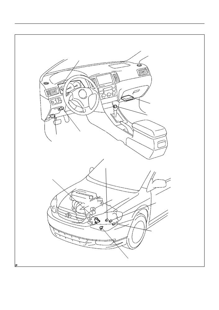
0527L-18
LOCATION
Combination Meter
F MIL
ECM
Transmission Control Switch
(O/D Main Switch)
Stop Lamp Switch
DLC3
Assy
Shift Solenoid Valve S1
Park/neutral Position
Switch Assy
Shift Solenoid Valve S2
Shift Solenoid Valve SL
Shift Solenoid Valve SLT
G27627

DIAGNOSTICS
- ELECTRONIC CONTROLLED AUTOMATIC
05-361
TRANSAXLE [ECT] (April, 2003)
05DTW-01
MANUAL SHIFTING TEST
1.
PERFORM MANUAL SHIFTING TEST
HINT:
By this test, it can be determined whether the trouble is within
the electrical circuit or is a mechanical problem in the transaxle.
(a) Disconnect the transmission wire connector.
(b) Inspect the manual driving operation.
Check that the shift and gear positions correspond to the
table below.
While driving, shift through the L, 2 and D positions.
Check that the gear change corresponds to the shift posi-
tion.
Shift Position
Gear Position
Q02283
D
O/D
2
O/D
L
1st
R
Reverse
P
Pawl Lock
HINT:
If the gear positions of the L, 2 and D are difficult to distinguish,
do the following road test.
If any abnormality is found in the above test, the problem is in
the transaxle itself.
(c)
Connect the transmission wire connector.
(d) Clear the DTC (See page 05-353).

05-358
DIAGNOSTICS
- ELECTRONIC CONTROLLED AUTOMATIC
TRANSAXLE [ECT] (April, 2003)
05DTU-01
MECHANICAL SYSTEM TESTS
1.
PERFORM MECHANICAL SYSTEM TESTS
(a) Measure the stall speed.
The object of this test is to check the overall performance of the transaxle and engine by measuring
the stall speeds in the D and R positions.
NOTICE:
F
Do the test at normal operating ATF temperature 50 to 80
°C (122 to 176 °F).
F
Do not continuously run this test for longer than 5 seconds.
F
To ensure safety, do this test in a wide, clear level area which provides good traction.
F
The stall test should always be carried out in pairs. One technician should observe the condi-
tions of wheels or wheel stoppers outside the vehicle while the other is doing the test.
(1)
Chock the 4 wheels.
(2)
Connect an OBD II scan tool or hand-held tester to the DLC3.
(3)
Fully apply the parking brake.
(4)
Keep your left foot pressed firmly on the brake pedal.
(5)
Start the engine.
(6)
Shift into the D position. Press all the way down on the accelerator pedal with your right foot.
(7)
Quickly read the stall speed at this time.
Stall speed: 2,550
150 rpm
(8)
Do the same test in the R position.
Stall speed: 2,550
150 rpm
Evaluation:
Problem
Possible cause
F Engine output may be insufficient
F Stator one-way clutch not operating properly
(a) Stall speed low in D and R positions
HINT: If the value is less than the specified value by 600 rpm or
more, the torque converter could be faulty.
F Line pressure too low
F Forward clutch slipping
(b) Stall speed high in D position
F No. 2 one-way clutch not operating properly
F U/D one-way clutch not operating properly
F Line pressure too low
F Direct clutch slipping
(c) Stall speed high in R position
F 1st and reverse brake slipping
F U/D brake slipping
F Line pressure too low
(d) Stall speed high in D and R positions
F Improper fluid level
F U/D one-way clutch not operating properly

DIAGNOSTICS
-
ELECTRONIC CONTROLLED AUTOMATIC
05-359
TRANSAXLE [ECT] (April, 2003)
(b) Measure the time lag.
(1)
When the shift lever is shifted while the engine is idling, there will be a certain time lapse or lag
before the shock can be felt. This is used for checking the condition of the direct clutch, forward
clutch, and 1st and reverse brake.
NOTICE:
F
Do the test at normal operating ATF temperature 50 to 80
°C (122 to 176 °F).
F
Be sure to allow 1 minute interval between tests.
F
Take 3 measurements and take the average value.
(2)
Connect an OBD II scan tool or hand-held tester to the DLC3.
(3)
Fully apply the parking brake.
(4)
Start the engine and check idle speed.
Idle speed: 650
± 50 rpm (In N position and A/C OFF)
(5)
Shift the shift lever from the N to D position. Using a stop watch, measure the time from when
the lever is shifted until the shock is felt.
(6)
Measure the time lag of N R in the same way.
Time lag:
N D Less than 1.2 seconds
N R Less than 1.5 seconds
Evaluation (If N
D time or N R time lag is longer than specified):
Problem
Possible cause
F Line pressure too low
N D time lag is longer
F Forward clutch worn
F U/D one-way clutch not operating properly
F Line pressure too low
F Direct clutch worn
N R time lag is longer
F 1st and reverse brake worn
F U/D one-way clutch not operating properly

DIAGNOSTICS
- ELECTRONIC CONTROLLED AUTOMATIC
05-419
TRANSAXLE [ECT] (April, 2003)
05DUA-01
O/D CANCEL SIGNAL CIRCUIT
CIRCUIT DESCRIPTION
While driving uphill with cruise control activated, in order to minimize gear shifting and provide smooth cruis-
ing overdrive may be prohibited temporarily under some conditions.
The cruise control ECU sends O/D cut signals to the ECM as necessary and the ECM cancels overdrive
shifting until these signals are discontinued.
WIRING DIAGRAM
Cruise Control ECU
ECM
14
18
R-Y
OD
C14
E5
OD1
D25841
INSPECTION PROCEDURE
1
INSPECT TERMINAL VOLTAGE(OD - BODY GROUND)
(a) Disconnect the cruise control ECU connector.
(b) Turn the ignition switch to the ON position.
(c)
Measure the voltage between terminal OD of cruise con-
trol ECU and body ground.
Cruise Control ECU:
Standard:
C14
Condition
Tester Connection
Specified Condition
IG switch ON
C14 - 14 (OD) -
10 to 14 V
IG switch OFF
Body ground
Below 1 V
OD
I30402
OK CHECK AND REPLACE CRUISE CONTROL ECU
ASSY (See page 05-752)
NG

05-420
DIAGNOSTICS
- ELECTRONIC CONTROLLED AUTOMATIC
TRANSAXLE [ECT] (April, 2003)
2
INSPECT TERMINAL VOLTAGE(OD1 - BODY GROUND)
(a) Measure the voltage between terminal OD1 of ECM and
body ground.
E3
E4
E5
E6
Standard:
Condition
Tester Connection
Specified Condition
IG switch ON
E5 - 18 (OD1) -
10 to 14 V
IG switch OFF
Body ground
Below 1 V
OK REPAIR OR REPLACE HARNESS OR
OD1
CONNECTOR (See page 01-30)
ECM:
C96070
NG
3
CHECK HARNESS AND CONNECTOR(OD1 - BODY GROUND)
(a) Disconnect the ECM connector.
E3
E4
E5
E6
(b) Measure the resistance according to the value(s) in the
table below.
Standard (Check for short):
Tester Connection
Specified Condition
E5 - 18 (OD1) - Body ground
10 kW or higher
OD1
ECM:
C95815
NG REPAIR OR REPLACE HARNESS OR
CONNECTOR (See page 01-30)
OK
PROCEED TO NEXT CIRCUIT INSPECTION SHOWN ON PROBLEM SYMPTOMS TABLE
(See page 05-374)

DIAGNOSTICS
- ELECTRONIC CONTROLLED AUTOMATIC
05-417
TRANSAXLE [ECT] (April, 2003)
05DU9-01
O/D MAIN SWITCH CIRCUIT
CIRCUIT DESCRIPTION
The O/D main switch (transmission control switch) is a momentary type switch. When pressing the O/D main
switch, the O/D OFF indicator light lights up and the ECM prohibits shifting into O/D, and when pressing it
once again, the O/D OFF indicator light goes off and the ECM allows shifting into O/D. Turning the IG switch
OFF will reset the O/D OFF indicator light.
WIRING DIAGRAM
A10
ECM
RH J/B
Transmission Control Switch
11
17
(O/D MAIN SW)
29
W-B
W-B
LG-B
3A
3A
E5
ODMS
4
2
A
J7
J/C
IG
C96096
INSPECTION PROCEDURE
1
CHECK HARNESS AND CONNECTOR(TRANSMISSION CONTROL SWITCH -
BODY GROUND)
(a) Disconnect the transmission control switch connector of
Wire Harness Side:
(Connector Front View):
shift lever assy.
(b) Measure the resistance according to the value(s) in the
table below.
Standard:
A10
Tester Connection
Specified Condition
4 - Body ground
Below 1 W
NG REPAIR OR REPLACE HARNESS OR
G27227
CONNECTOR (See page 01-30)
OK