Toyota Corolla (2004+). Manual - part 14
19-6
STARTING & CHARGING
- STARTER ASSY (1ZZ-FE) (April, 2003)
3.
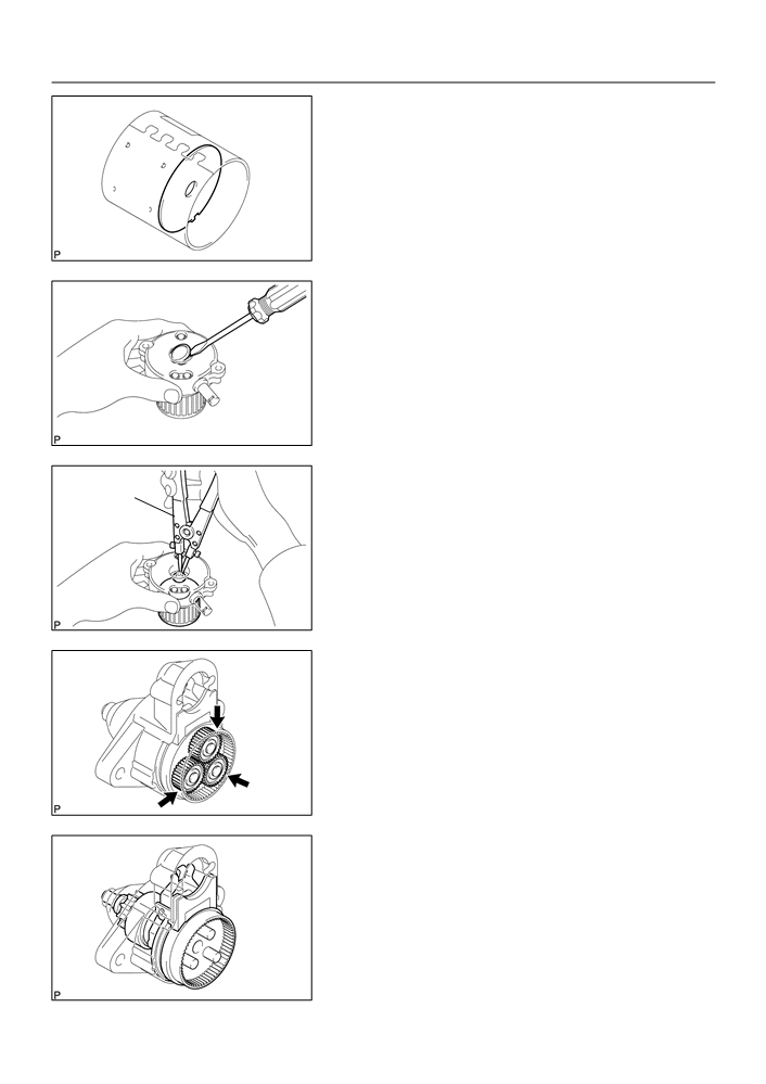
REMOVE STARTER ARMATURE PLATE
(a) Remove the starter armature plate from the starter yoke.
A83803
4.
REMOVE STARTER COMMUTATOR END FRAME
COVER
(a) Using a screwdriver, remove the starter commutator end
frame cover.
A83801
5.
REMOVE STARTER ARMATURE ASSY
Snap Ring
(a) Using snap ring pliers, remove the snap ring.
Pliers
(b) Remove the washer and starter armature from the starter
commutator end frame.
A83802
6.
REMOVE PLANETARY GEAR
(a) Remove the 3 planetary gears from the starter center
bearing clutch.
A83804
7.
REMOVE STARTER CENTER BEARING CLUTCH
SUB-ASSY
(a) Remove the starter center bearing clutch together with
the starter drive lever set pin from the starter drive hous-
ing.
A83805
19-7
STARTING & CHARGING
- STARTER ASSY (1ZZ-FE) (April, 2003)
8.
REMOVE STARTER DRIVE LEVER SET PIN
(a) Remove the starter drive lever set pin from the starter cen-
ter bearing clutch.
A73990
9.
INSPECT REPAIR SERVICE STARTER KIT
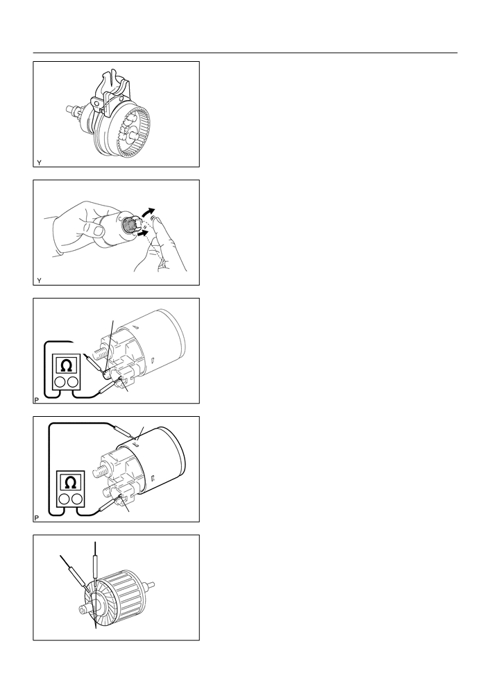
(a) Check the operation.
(1)
Push in the plunger, then check that it returns quick-
ly to its original position.
If necessary, replace the repair service starter kit.
A58586
(b) Check the continuity.
Terminal C
(1)
Using an ohmmeter, check that there is continuity
between terminals 50 and C.
Continuity
If there is no continuity, replace the repair service starter kit.
Ohmmeter
Terminal 50
A84614
Switch Body
(2)
Using an ohmmeter, check that there is continuity
Continuity
between terminal 50 and the switch body.
If there is no continuity, replace the repair service starter kit.
Ohmmeter
Terminal 50
A84615
10. INSPECT STARTER ARMATURE ASSY
Continuity
(a) Check the continuity.
(1)
Using an ohmmeter, check that there is continuity
between the segments of the commutator.
If there is no continuity between any segments, replace the
starter armature.
Segment
A79764

19-8
STARTING & CHARGING
- STARTER ASSY (1ZZ-FE) (April, 2003)
(2)
Using an ohmmeter, check that there is no continu-
No Continuity
ity between the commutator and armature coil core.
If there is continuity, replace the starter armature.
(b) Check the commutator surface for dirt or burn.
If the surface is dirty or burnt, smooth the surface with 400-grit
sandpaper or lathe.
Commutator
Coil Core
A79765
(c)
Check the commutator depth.
(1)
Using vernier calipers, measure the commutator
depth.
Standard depth: 3.1 mm (0.122 in.)
Depth
Maximum depth: 3.8 mm (0.150 in.)
If the depth is greater than maximum, replace the starter arma-
ture.
A58584
11. INSPECT STARTER COMMUTATOR END FRAME
ASSY
(a) Check the brush length.
(1)
Using vernier calipers, measure the brush length.
Length
Standard length: 9.0 mm (0.354 in.)
Minimum length: 4.0 mm (0.158 in.)
If the length is less than minimum, replace the starter commuta-
tor end frame.
A76677
(b) Check the continuity.
No Continuity
(1)
Using an ohmmeter, check that there is no continu-
ity between the positive (+) and negative (-) brush.
If there is continuity, repair or replace the starter commutator
end frame.
A79766
12. INSPECT STARTER CENTER BEARING CLUTCH
SUB-ASSY
Free
(a) Check the starter clutch.
(1)
Rotate the clutch pinion gear clockwise, then check
that it turns freely. Try to rotate the clutch pinion gear
counterclockwise, then check that it locks.
If necessary, replace the starter center bearing clutch.
Lock
A83810

19-9
STARTING & CHARGING
- STARTER ASSY (1ZZ-FE) (April, 2003)
(b) Check the wear or damage.
(1)
Inspect the gear teeth on the planetary gear, inter-
nal gear and starter clutch for wear or damage.
If damaged, replace the starter center bearing clutch.
13. INSTALL STARTER DRIVE LEVER SET PIN
(a) Install the starter drive lever set pin to the starter center
bearing clutch as shown in the illustration.
A84665
14. INSTALL STARTER CENTER BEARING CLUTCH
SUB-ASSY
(a) Install the starter center bearing clutch together with the
starter drive lever set pin to the starter drive housing.
A83805
15. INSTALL PLANETARY GEAR
(a) Apply grease to the planetary gears and pin parts of the
planetary shaft.
(b) Install the 3 planetary gears to the starter center bearing
clutch.
A83804

19-10
STARTING & CHARGING
- STARTER ASSY (1ZZ-FE) (April, 2003)
16. INSTALL STARTER ARMATURE ASSY
Snap Ring
(a) Apply grease to the washer and the armature shaft.
Pliers
(b) Install the starter armature and the washer to the starter
commutator end frame.
(c)
Using snap ring pliers, install a new snap ring.
A83802
(d) Check the snap ring length.
(1)
Using vernier calipers, measure the snap ring
Length
length.
Maximum length: 5.0 mm (0.197 in.)
If the length is greater than maximum, replace it with a new snap
ring.
A58810
17. INSTALL STARTER COMMUTATOR END FRAME
COVER
(a) Install the starter commutator end frame cover to the
starter commutator end frame.
A84616
18. INSTALL STARTER ARMATURE PLATE
Key
(a) Align the keyway of the starter armature plate with the key
Keyway
inside the starter yoke, then install the armature plate to
the starter yoke.
A73991
19. INSTALL STARTER COMMUTATOR END FRAME
Rubber
ASSY
Cutout
(a) Align the rubber with the cutout of the starter yoke, then
install the starter commutator end frame to the starter
yoke.
A79727

19-11
STARTING & CHARGING
- STARTER ASSY (1ZZ-FE) (April, 2003)
20. INSTALL STARTER YOKE ASSY
(a) Align the key of the starter yoke with the keyway of the
starter drive housing, then install the starter yoke to the
starter drive housing.
Keyway
Key
A84617
(b) Tighten the 2 through bolts.
Torque: 6.0 N m (61 kgf cm, 53 in. lbf)
A83799
21. INSTALL REPAIR SERVICE STARTER KIT
(a) Apply grease to the plunger and hook.
(b) Hang the plunger hook of the repair service starter kit to
the starter drive lever set pin.
(c)
Install the plunger and return spring.
A84618
(d) Install the repair service starter kit with the 2 screws.
Torque: 7.5 N m (76 kgf cm, 66 in. lbf)
A83798
(e) Connect the lead wire to terminal C with the nut.
Torque: 10 N m (102 kgf cm, 7 ft lbf)
A83797

19-4
STARTING & CHARGING
- STARTER ASSY (1ZZ-FE) (April, 2003)
190QQ-02
REPLACEMENT
1.
DISCONNECT BATTERY NEGATIVE TERMINAL
2.
REMOVE ENGINE UNDER COVER RH
3.
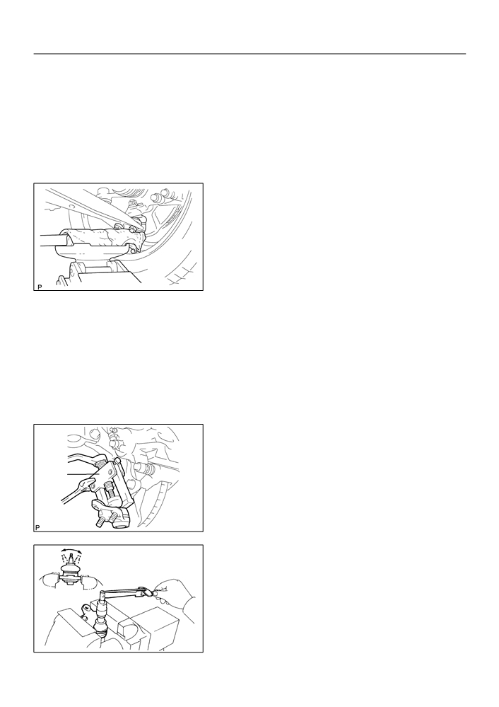
REMOVE STARTER ASSY
Terminal Cover
(a) Disconnect the starter connector.
(d)
(b) Open the terminal cover.
(c)
Remove the nut, then disconnect the starter wire.
(c)
(d) Remove the 2 bolts, then remove the starter.
(d)
(a)
A51076
4.
INSTALL STARTER ASSY
Torque:
37 Nm (378 kgf cm, 27 ft lbf) for bolt
9.8 Nm (100 kgf cm, 7 ft lbf) for nut
5.
INSTALL ENGINE UNDER COVER RH
6.
CONNECT BATTERY NEGATIVE TERMINAL
Torque: 5.4 N m (55 kgf cm, 48 in. lbf)
26-17
FRONT SUSPENSION
- LOWER BALL JOINT ASSY FRONT LH
LOWER BALL JOINT ASSY FRONT LH
2607Y-04
REPLACEMENT
HINT:
COMPONENTS: See page 26-3
1.
INSPECT LOWER BALL JOINT ASSY FRONT LH
(a) Jack up front side of the vehicle.
(b) Check the rattle of the lower ball joint assy front LH.
C54719
2.
REMOVE FRONT WHEEL
3.
REMOVE FRONT AXLE HUB LH NUT(See page 30-6)
SST
09930-00010
4.
DISCONNECT SPEED SENSOR FRONT LH (W/ ABS)(See page 30-6)
5.
SEPARATE TIE ROD END SUB-ASSY LH(See page 30-6)
SST
09628-62011
6.
SEPARATE FRONT SUSPENSION ARM SUB-ASSY LOWER NO.1 LH(See page 30-6)
7.
SEPARATE FRONT AXLE ASSY LH(See page 30-6)
8.
REMOVE LOWER BALL JOINT ASSY FRONT LH
(a) Remove the cotter pin and castle nut.
(b) Using SST, remove the lower ball joint assy from the
steering knuckle LH.
SST
SST
09628-62011
C95204
9.
INSPECT LOWER BALL JOINT ASSY FRONT LH
(a) As shown in the illustration, flip the ball joint stud back and
forth 5 times, before installing the nut.
(b) Using a torque wrench, turn the nut continuously at a rate
of 3 - 5 seconds per 1 turn and take the torque reading
on the 5th turn.
Turning torque:
0.98 - 4.9 Nm (10 - 50 kgf cm, 8.7 - 43 in. lbf)
ZX1712
26-18
FRONT SUSPENSION
- LOWER BALL JOINT ASSY FRONT LH
10. INSTALL LOWER BALL JOINT ASSY FRONT LH
(a) Install the lower ball joint assy front LH to the steering knuckle LH, tighten the castle nut.
Torque: 103 N m (1050 kgf cm, 76 ft lbf)
(b) Install a new cotter pin.
11. INSTALL FRONT AXLE ASSY LH(See page
30-6)
12. INSTALL FRONT SUSPENSION ARM SUB-ASSY LOWER NO.1 LH(See page
30-6)
13. INSTALL TIE ROD END SUB-ASSY LH(See page
30-6)
14. INSTALL SPEED SENSOR FRONT LH (W/ ABS)(See page 30-6)
15. INSTALL FRONT AXLE HUB LH NUT(See page
30-6)
SST
09931-00020
16. INSTALL FRONT WHEEL
Torque: 103 N m (1,050 kgf cm, 76 ft lbf)
17. INSPECT AND ADJUST FRONT WHEEL ALIGNMENT(See page 26-5)
18. CHECK ABS SPEED SENSOR SIGNAL (W/ ABS)(See page
05-297)
26-3
FRONT SUSPENSION
- FRONT SUSPENSION
FRONT SUSPENSION
2607U-01
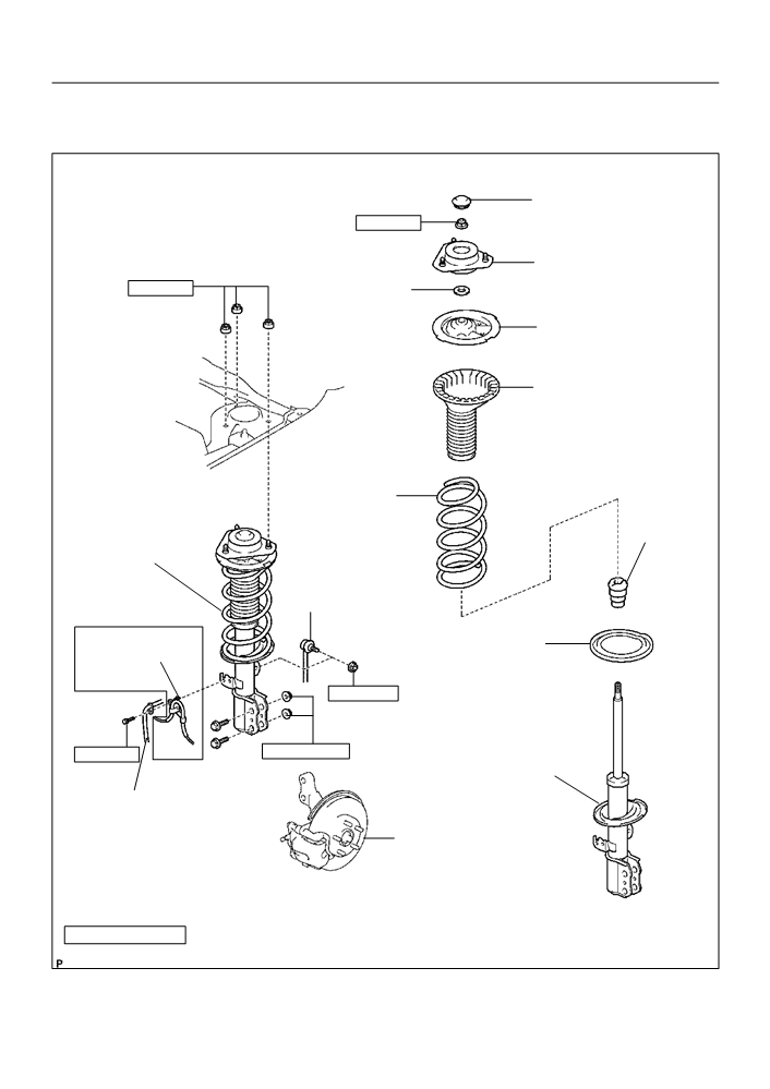
COMPONENTS
Front Suspension
Support Dust Cover LH
F
47 (479, 35)
Front Suspension
Support Sub-assy LH
39 (398, 29)
Front Suspension
Support LH
Dust Seal
Front Coil Spring
Seat Upper LH
Front Coil Spring
Insulator Upper LH
Front Coil
Spring LH
Front Spring
Bumper LH
Front Shock
Absorber with
Front Stabilizer
Coil Spring
Link Assy LH
w/ ABS:
Front Coil
Speed Sensor
Spring Insulator
Front LH
Lower LH
74 (755, 55)
153 (1,560, 113)
29 (296, 21)
Shock Absorber
Assy Front LH
Front Flexible Hose
Front Axle Assy
Nm (kgfcm, ftlbf)
: Specified torque
F Non-reusable part
C95203

26-4
FRONT SUSPENSION
- FRONT SUSPENSION
58 (591, 43)
58 (591, 43)
Rack & Pinion Power
Steering Gear Assy
19 (194, 14)
Front Stabilizer Bracket No.1 RH
Front Stabilizer Bar Bush No.1
Stabilizer Bar Front
19 (194, 14)
Front Stabilizer
Link Assy RH
Front Stabilizer
Bracket No.1 LH
74 (755, 55)
Front Stabilizer Bar
Bush No.1
Front Stabilizer
Link Assy LH
157 (1,601, 116)
74 (755, 55)
49 (500, 36)
157 (1,601, 116)
FCotter Pin
74 (755, 55)
Front Suspension
Crossmember
Sub-assy
FCotter Pin
113 (1,152, 83)
137 (1,397, 101)
52 (530, 38)
137 (1,397, 101)
F
216 (2,203, 159)
103 (1,050, 76)
Front Suspension Arm
Sub-assy Lower No.1 LH
Lower Ball Joint Assy
Front LH
113 (1,152, 83)
29 (296, 21)
Front Flexible Hose
89 (908, 66)
29 (296, 21)
Front Drive Shaft
w/ ABS:
Assy LH
Nm (kgfcm, ftlbf)
: Specified torque
Speed Sensor Front LH
F Non-reusable part
C95200
26-5
FRONT SUSPENSION
- FRONT WHEEL ALIGNMENT
FRONT WHEEL ALIGNMENT
2607T-01
ADJUSTMENT
1.
INSPECT TIRE(See page 28-1)
2.
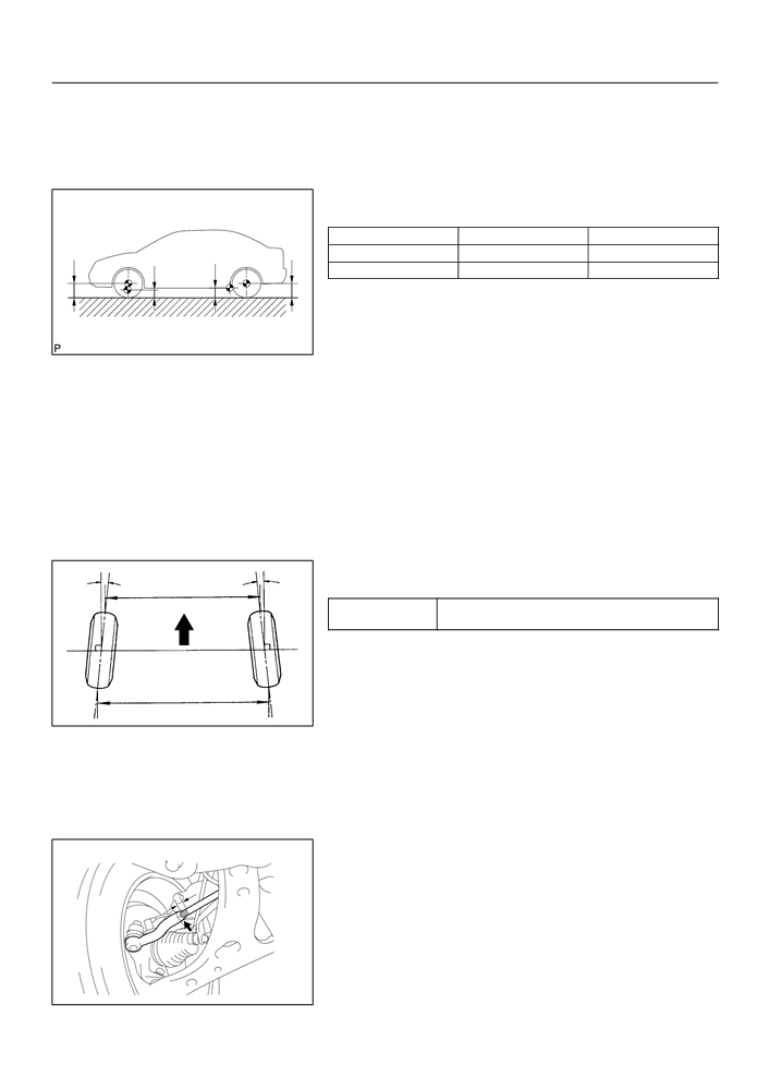
MEASURE VEHICLE HEIGHT
Vehicle height:
USA, Canada
Mexico
Front (A - B)
87 mm (3.43 in.)
72 mm (2.84 in.)
A
Rear (D - C)
43 mm (1.69 in.)
29 mm (1.14 in.)
B
C
D
Measuring points:
A: Ground clearance of front wheel center
B: Ground clearance of lower suspension arm front
C95205
bolt center
C: Ground clearance of axle beam set bolt center
D: Ground clearance of rear wheel center
NOTICE:
Before inspecting the wheel alignment, adjust the vehicle
height to the specified value.
If the vehicle height is not the specified value, try to adjust it by
pushing down on or lifting the body.
3.
INSPECT TOE-IN
A
B
D
Toe-in:
Front
Toe-in
A + B: 0° ± 12’ (0° ± 0.2°)
(total)
C - D: 0 ± 2 mm (0 ± 0.08 in.)
If the toe-in is not within the specified value, adjust it at the rack
ends.
4.
ADJUST TOE-IN
C
(a) Remove the rack boot set clips.
SA3213
(b) Loosen the tie rod end lock nuts.
(c)
Turn the right and left rack ends by an equal amount to
adjust the toe-in.
HINT:
Try to adjust the toe-in to the center of the specified value.
(d) Make sure that the lengths of the right and left rack ends
are the same.
Rack end length difference: 1.5 mm (0.059 in.) or less
(e) Torque the tie rod end lock nuts.
Torque: 74 N·m (755 kgf·cm, 55 ft·lbf)
(f)
Place the boots on the seats and install the clips.
HINT:
Make sure that the boots are not twisted.
C90321

26-6
FRONT SUSPENSION
- FRONT WHEEL ALIGNMENT
5.
INSPECT WHEEL ANGLE
A B
B A
(a) Turn the steering wheel fully and measure the turning
angle.
Front
Wheel turning angle:
USA, Canada
Mexico
37°06’ ± 2°
37°16’ ± 2°
Inside wheel
(37.10° ± 2°)
(37.27° ± 2°)
A: Inside
Outside wheel:
B: Outside
31°49’ (31.82°)
32°08’ (32.13°)
Reference
SA0028
If the right and left inside wheel angles differ from the specified
value, check the right and left rack end lengths.
6.
INSPECT CAMBER, CASTER AND STEERING AXIS
INCLINATION
Gauge
(a) Install the camber-caster-kingpin gauge or position ve-
hicle on wheel alignment tester.
Alignment
(b) Inspect the camber, caster and steering axis inclination.
Tester
Camber, caster and steering axis inclination:
USA, Canada
Mexico
Camber
-0°32’ ± 45’
-0°22’ ± 45’
(-0.53° ± 0.75°)
(-0.37° ± 0.75°)
Z03382
Right-left error
45’ (0.75°) or less
45’ (0.75°) or less
Caster
2°50’ ± 45’
2°43’ ± 45’
(2.83° ± 0.75°)
(2.72° ± 0.75°)
Right-left error
45’ (0.75°) or less
45’ (0.75°) or less
Steering axis inclination
11°21’ ± 45’
10°59’’ ± 45’
(11.35° ± 0.75°)
(10.98° ± 0.75°)
Right-left error
45’ (0.75°) or less
45’ (0.75°) or less
If the caster and steering axis inclination are not within the spe-
cified values, after the camber has been correctly adjusted, re-
check the suspension parts for damaged and/or worn out parts.
7.
ADJUST CAMBER
NOTICE:
After the camber has been adjusted, inspect the toe-in.
(a) Remove the front wheel.
(b) Remove the 2 nuts on the lower side of the shock absorb-
er assy front LH.
NOTICE:
When removing nut, stop the bolt from rotating and loosen
the nut.
(c)
Clean the installation surfaces of the shock absorber assy
front LH and the steering knuckle.
(d) Temporarily install the 2 nuts.
F13683

26-7
FRONT SUSPENSION
- FRONT WHEEL ALIGNMENT
(e) Adjust the camber by pushing or pulling the lower side of
the shock absorber in the direction in which the camber
adjustment is required.
(f)
Tighten the nuts.
Torque: 153 N m (1,560 kgf cm, 113 ft lbf)
(g) Install the front wheel.
Torque: 103 N·m (1,050 kgf·cm, 76 ft·lbf)
F13684
(h) Check the camber.
HINT:
1
F
Try to adjust the camber to the center of the specified val-
ue.
F
Adjusting value for the set bolts is -1_30’ - 0_30’ (-1.5_
- 0.5_).
2
If the camber is not within the specified value, using the follow-
ing table, estimate how much additional camber adjustment will
F13685
be required, and select the camber adjusting bolt.
Set Bolt
Adjusting Bolt
Bolt
90105-15001
90105-15004
90105-15005
90105-15006
1 Dot
2 Dots
3 Dots
Adjusting
Value
1
2
1
2
1
2
1
2
–1°30’ - -1°15’
-1°15’ - -1°00’
-1°00’ - -45’
-45’ - -30’
-30’ - -15’
-15’ - 0’
0’ - 15’
15’ - 30’
30’ - 45’
45’ - 1°00’
1°00’ - 1°15’
1°15’ - 1°30’
F12938
(i)
Perform the steps mentioned above again. At step (e), re-
place 1 or 2 selected bolts.
HINT:
When replacing the 2 bolts, replace 1 bolt at a time.
26-2
FRONT SUSPENSION
- FRONT SUSPENSION SYSTEM
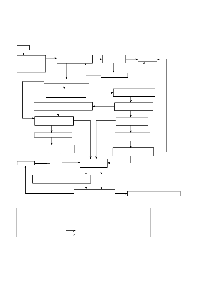
2607S-01
REPAIR
HINT:
This is a flow chart for vehicle pull.
START
Preliminary Check
ROAD TEST
NO
Is there steering
NO
*
COMPLETE
_ Tire pressure
Does the vehicle lead/pull?
off center?
_ Vehicle height
YES
YES
_ Brake dragging
Adjust front tie rods.
YES
Are the tires uni-directional type?
NO
NO
Cross switch front tire & wheel
ROAD TEST
assemblies (left & right).
Does the vehicle still lead/pull?
YES
Choose the position of front tire & wheel
YES
Does the vehicle lead/pull in
assemblies where there is least amount of pull.
same direction as before?
NO
Check front wheel alignment.
YES
NO
Is the lead/pull stronger
Is it within specification?
than before?
NO
YES
Adjust front wheel alignment.
Reverse the front left side
tire and rebalance it.
ROAD TEST
ROAD TEST
NO
Does the vehicle still lead/pull?
Does the vehicle still lead/pull?
NO
YES
YES
Does the vehicle
COMPLETE
lead/pull to the left?
NOTICE : Do not exceed 1 ° of cross camber.
YES
NO
Do not exceed adjustment range.
Increase right front camber and decrease
Increase left front camber and decrease
left front camber until lead/pull is eliminated.
right front camber until lead/pull is eliminated.
NO
ROAD TEST
YES
Contact your local retail tire distributor.
Does the vehicle still lead/pull?
Select a flat road where the vehicle can be driven in a straight line for 100 meters at a constant speed
of 35mph. Please confirm safety and set the steering wheel to its straight position. Drive the vehicle in
a straight line for 100 meters at a constant speed of 35 mph without holding the steering wheel.
(1) The vehicle can keep straight but the steering wheel has some angle.
STEERING OFF CENTER (See page 50-4)
(2) The vehicle cannot keep straight.
STEERING PULL