Subaru WRX STI (2019 year). Instruction - part 9


  Index      Subaru     Subaru WRX STI - instruction 2019 year in english


Search            copyright infringement  


Content   ..  7  8  9  10   ..


Subaru WRX STI (2019 year). Instruction - part 9


(135,1)

北米Model "A1720BE-A" EDITED: 2018/ 3/ 9

&

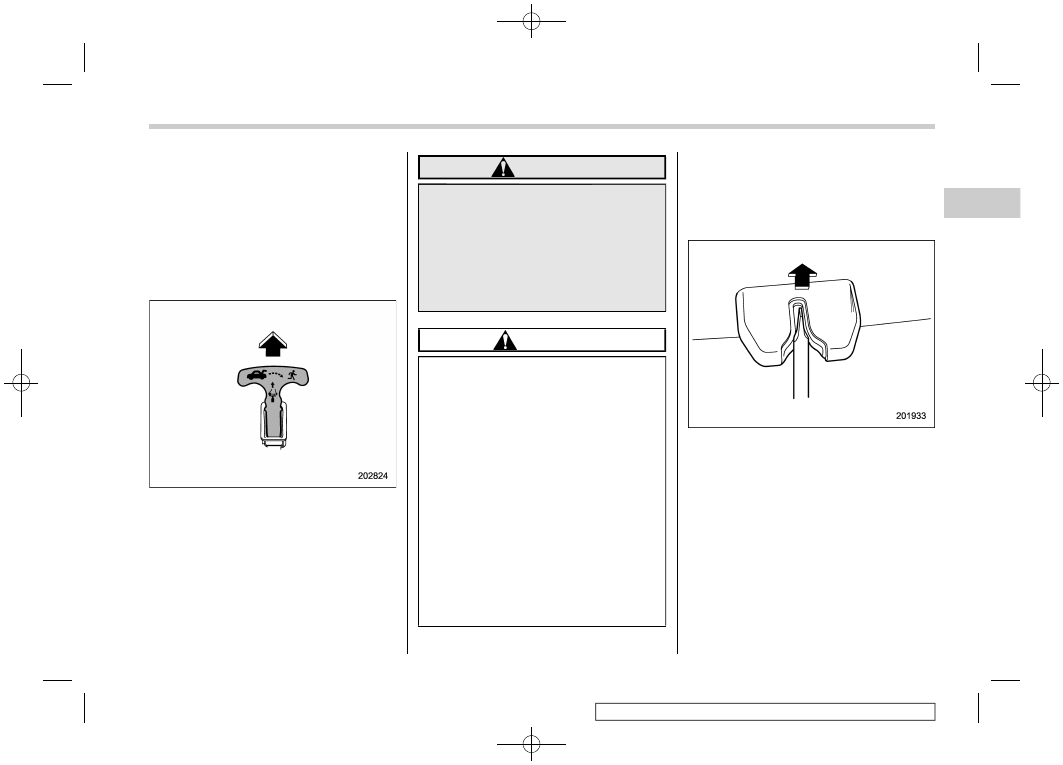
Internal trunk lid release
handle

The internal trunk lid release handle is a
device designed to open the trunk lid from
inside the trunk. In the event children or
adults become locked inside the trunk, the
handle allows them to open the lid. The
handle is located on the inside of the trunk
lid.

To open the trunk lid from inside the trunk,
pull the yellow handle as indicated by the
arrow on the handle. This operation
unlocks the trunk lid. Then, push up the lid.
The handle is made of material that
remains luminescent for approximately
an hour in the dark trunk space after it is
exposed to ambient light even for a short
time.

WARNING

Never allow any child to get in the
trunk and play with the release
handle. If the driver starts the vehi-
cle without knowing that a child is
inside the trunk and the child opens
the lid using the release handle, the
child could fall out and be killed or
seriously injured.

CAUTION

.

Do not close the lid while gripping

the release handle. The handle
may be damaged.

.

Do not use the handle as a hook

to fasten straps or ropes to
secure your cargo in the trunk.
Such use may result in damage of
the handle.

.

Load the trunk so that cargo

cannot strike the release handle.
If the cargo hits the handle while
the vehicle is being driven, the
handle may be pulled and the
trunk lid may open. That may
cause cargo to fall out of the
trunk, which could create a traffic
safety hazard.

!

Inspection

Perform the following steps at least twice a
year to check the release handle for
correct operation.
1. Open the trunk lid.

2. Use a flat-head screwdriver with a thin
blade. Slide the flat-head screwdriver
blade from the slit aperture of the lock
assembly fully to the end until you hear a
click.

– CONTINUED –

Keys and doors/Trunk lid

2-37

2

(136,1)

北米Model "A1720BE-A" EDITED: 2018/ 3/ 9

This places the latch in the locked position.

3. Move the release handle, from outside
the vehicle, in the direction of the arrow to
check if the latch is released.

If the latch is not released, contact your

SUBARU dealer.
In that case, use the key to release the
latch, then close the trunk lid.
Also, if the movement of the release
handle feels restricted or not entirely
smooth during operation, or the handle
and/or handle base is cracked, contact
your SUBARU dealer.

Moonroof (if equipped)

WARNING

Never let anyone’s hands, arms,
head or any objects protrude from
the moonroof. A person could be
seriously injured if the vehicle stops
suddenly or turns sharply or if the
vehicle is involved in an accident.

To avoid serious personal injury
caused by accidental, child’s mis-
chief, or improper operation, the
driver is responsible for obeying
the following instructions without
exception.

.

Before closing the moonroof,

make sure that no one’s hands,
arms, head or other objects will
be accidentally caught in the
moonroof.

.

Always carry the key when you

leave the vehicle for safety rea-
sons and never allow an unat-
tended child to remain in the
vehicle. Failure to follow this
procedure could result in injury
to a child operating the moon-
roof.

.

Never try to check the anti-en-

Keys and doors/Moonroof

2-38

(137,1)

北米Model "A1720BE-A" EDITED: 2018/ 3/ 9

trapment function by deliberately
placing part of your body in the
moonroof.

CAUTION

.

Do not sit on the edge of the open

moonroof.

.

Do not operate the moonroof if

falling snow or extremely cold
conditions have caused it to
freeze shut.

.

The anti-entrapment function

does not operate when the moon-
roof is being tilted down. Be sure
to confirm that it is safe to do so
before tilting the moonroof down.

.

If the moonroof does not close,

we recommend that you have the
system checked by a SUBARU
dealer.

The moonroof has both tilting and sliding
functions.

The moonroof operates only when the
ignition switch is in the “ON” position.

&

Moonroof switches

!

Tilting moonroof

1)

Raise

2)

Lower

The tilting function is activated only when
the moonroof is fully closed.

To raise:
Press and hold the rear side of the “UP/
DOWN” switch for a short time. The
moonroof raises completely.

To lower:
Press and hold the front side of the “UP/
DOWN” switch until the preferred position
has reached.

Release the switch after the moonroof has
been raised or has been lowered comple-

tely. Pressing the switch continuously may
cause damage to the moonroof.

NOTE

One-touch operation does not take
place when the moonroof is lowered.
Press the switch continuously to lower
the moonroof.

!

Sliding moonroof

1)

Open

2)

Close

Tilt down the moonroof completely before
performing the sliding operation.
To open:
Press the rear side of the “OPEN/CLOSE”
switch. The sun shade will also be opened
together with the moonroof. The moonroof
will stop once at a midway position. Press

– CONTINUED –

Keys and doors/Moonroof

2-39

2

(138,1)

北米Model "A1720BE-A" EDITED: 2018/ 3/ 9

the rear side of the switch again to open
the moonroof completely.

To close:
Press the front side of the “OPEN/CLOSE”
switch.
To stop the moonroof at a selected mid-
way position while opening or closing it,
momentarily push the switch to the
“OPEN” side or “CLOSE” side.

After washing the vehicle or after it rains,
wipe away water on the roof prior to
opening the moonroof to prevent drops of
water from falling into the passenger
compartment.

NOTE

Driving with the moonroof fully open
can cause an annoying sound to be
generated at high speeds. If this oc-
curs, use the moonroof at the midway
stop position when the moonroof is
opened.

!

Anti-entrapment function

When the moonroof senses a substantial
enough object trapped between its glass
and the vehicle’s roof during closure, it
automatically moves back to the fully open
position and stops there. The anti-entrap-
ment function may also be activated by a
strong shock on the moonroof even when
there is nothing trapped.

CAUTION

Never attempt to test this function
using fingers, hands or other parts
of your body.

NOTE

For the sake of safety, it is recom-
mended that you avoid driving with the
moonroof fully opened.

&

Sun shade

You can slide the sun shade forward or
backward by hand while the moonroof is
closed.
If the moonroof is opened, the sun shade
also moves back.

Keys and doors/Moonroof

2-40

(141,1)

北米Model "A1720BE-A" EDITED: 2018/ 3/ 9

Ignition switch......................................................... 3-4

Conventional type ignition switch........................... 3-5
Push-button ignition switch.................................... 3-6

Hazard warning flasher .......................................... 3-8
Meters and gauges ................................................. 3-8

Combination meter illumination.............................. 3-8
Canceling the function for meter/gauge needle

movement upon turning on the ignition switch ..... 3-9

Speedometer ......................................................... 3-9
Odometer............................................................... 3-9
Double trip meter ................................................... 3-9
Tachometer ........................................................... 3-10
Fuel gauge............................................................ 3-10
Temperature gauge ............................................... 3-11
ECO gauge ........................................................... 3-12

REV indicator light and buzzer (STI) ................... 3-12
Warning and indicator lights................................ 3-13

Seatbelt warning light and chime .......................... 3-14
SRS airbag system warning light........................... 3-15
Front passenger’s frontal airbag ON and OFF

indicators ........................................................... 3-16

CHECK ENGINE warning light/Malfunction

indicator light ..................................................... 3-16

Charge warning light............................................. 3-17
Oil pressure warning light ..................................... 3-17
Engine low oil level warning indicator

(except STI) ........................................................ 3-17

Windshield washer fluid warning indicator ............ 3-18
AT OIL TEMP warning light (CVT models) .............. 3-18
Rear differential oil temperature warning light

(STI) ................................................................... 3-18

Low tire pressure warning light (U.S.-spec.

models) ............................................................. 3-19

ABS warning light................................................. 3-20
Brake system warning light................................... 3-21
Electronic parking brake indicator light (models

with electronic parking brake system) ................ 3-23

Low fuel warning light .......................................... 3-24
Hill start assist warning light/Hill start assist

OFF indicator light (models without electronic
parking brake system) ....................................... 3-24

Auto Vehicle Hold ON indicator light (models

with electronic parking brake system) ................ 3-24

Auto Vehicle Hold operation indicator light

(models with electronic parking brake system)... 3-24

Door open warning light ....................................... 3-25
All-Wheel Drive warning light (if equipped)............ 3-25
Power steering warning light (except STI) ............. 3-25
LED headlight warning light (if equipped).............. 3-26
Vehicle Dynamics Control warning light/Vehicle

Dynamics Control operation indicator light ........ 3-26

Vehicle Dynamics Control OFF indicator

light/Traction mode indicator light...................... 3-27

Warning chimes and warning indicator of the

keyless access with push-button start system
(if equipped) ...................................................... 3-28

Security indicator light.......................................... 3-33
SI-DRIVE indicator (if equipped) ............................ 3-34
Gear position indicator (MT models)/Shift-up

indicator (STI).................................................... 3-34

Select lever/gear position indicator

(CVT models)..................................................... 3-34

Turn signal indicator lights ................................... 3-35
High beam indicator light...................................... 3-35

Instruments and controls

3

(142,1)

北米Model "A1720BE-A" EDITED: 2018/ 3/ 9

High Beam Assist indicator light (green)

(if equipped) ....................................................... 3-35

High Beam Assist warning indicator (yellow)

(if equipped) ....................................................... 3-35

Cruise control indicator ........................................ 3-35
Cruise control set indicator ................................... 3-35
Automatic headlight beam leveler warning light

(models with LED headlights).............................. 3-35

Front fog light indicator light (if equipped) ............ 3-35
Headlight indicator light ........................................ 3-36
Driver’s control center differential auto indicator

(STI) ................................................................... 3-36

Driver’s control center differential indicator and

warning (STI) ...................................................... 3-36

REV indicator light (STI) ........................................ 3-37
Steering Responsive Headlight warning indicator/

Steering Responsive Headlight OFF indicator
(if equipped) ....................................................... 3-37

BSD/RCTA warning indicator (if equipped)............. 3-37
BSD/RCTA OFF indicator (if equipped) .................. 3-37
RAB warning indicator (if equipped) ...................... 3-37
RAB OFF indicator light (if equipped) .................... 3-37

Combination meter display (color LCD) ............. 3-38

Basic operation..................................................... 3-39
Welcome screen (opening animation) and

Good-bye screen (ending animation) ................... 3-39

Warning screen..................................................... 3-39
Basic screens ....................................................... 3-40
Warning indication ................................................ 3-41
Menu screens ....................................................... 3-41

Multi-function display (color LCD) ...................... 3-44

Welcome screen ................................................... 3-45
Self-check screen ................................................. 3-45
Interruption screen ............................................... 3-46
Basic operation .................................................... 3-46
Basic screens....................................................... 3-47
Setting screen ...................................................... 3-52
How to get the source code using the open

source............................................................... 3-63

Clock...................................................................... 3-64
Light control switch ............................................. 3-65

Headlights ............................................................ 3-65
High/low beam change (dimmer) ........................... 3-67
Headlight flasher .................................................. 3-70
Daytime running light system ............................... 3-70

Steering Responsive Headlight (SRH)

(if equipped) ....................................................... 3-71

To turn on/off the SRH .......................................... 3-71

Turn signal lever ................................................... 3-72

One-touch lane changer........................................ 3-72

Illumination brightness control ........................... 3-72

Automatic dimming function ................................. 3-73
Auto dimmer cancel function ................................ 3-73

Headlight beam leveler (if equipped) .................. 3-73

Automatic headlight beam leveler (models with

LED headlights) ................................................. 3-73

Fog light switch (if equipped).............................. 3-73
Wiper and washer................................................. 3-74

Windshield wiper and washer switches ................. 3-75

Instruments and controls

(143,1)

北米Model "A1720BE-A" EDITED: 2018/ 3/ 9

Mirrors ................................................................... 3-77

Inside mirror ......................................................... 3-77
Auto-dimming mirror/compass (if equipped) .......... 3-77
Auto-dimming mirror/compass with HomeLink

®

(if equipped) ....................................................... 3-78

Outside mirrors..................................................... 3-85

Defogger and deicer............................................. 3-86
Tilt/telescopic steering wheel .............................. 3-87
Horn ....................................................................... 3-88

Instruments and controls

(144,1)

北米Model "A1720BE-A" EDITED: 2018/ 3/ 9

Ignition switch

Conventional type ignition switch

Push-button ignition switch
1)

Operation indicator

2)

Push-button ignition switch

The design of the push-button ignition
switch may be slightly different depending
on the models.

WARNING

.

Before leaving the vehicle, ob-

serve the following instructions
for safety.

– Remove the key from the igni-

tion switch (models with con-
v e n t i o n a l t y p e i g n i t i o n
switch).

– Carry out the access key fob

(models with push-button
ignition switch).

– Never allow an unattended

child to remain in the vehicle.

Failure to observe these instruc-

tions could result in injury to a
child or others. Children could
operate the power windows, the
moonroof or other controls, or
even make the vehicle move.

.

Never turn the ignition switch to

the “LOCK”/“OFF” position while
driving or being towed. Doing so
will lock the steering wheel, pre-
venting steering control. In addi-
tion, when the engine stops, it
takes a much greater effort than

usual to steer.

CAUTION

.

To prevent the vehicle battery

from discharging, keep the igni-
tion switch in the “LOCK”/“OFF”
position when the engine is not
running.

.

Do not use electrical accessories

for a long time with the ignition
switch in the “ON” or “ACC”
position. Doing so can cause the
battery to go dead.

Instruments and controls/Ignition switch

3-4

(145,1)

北米Model "A1720BE-A" EDITED: 2018/ 3/ 9

&

Conventional type ignition
switch

CAUTION

Do not attach a large key holder or
key case to either key. If it hits your
knees or hands while driving, it
could turn the ignition switch to the
“ACC” or “LOCK” position, stop-
ping the engine. Also, if the key is
attached to a keyholder or to a large
bunch of other keys, centrifugal
force may act on it as the vehicle
moves, resulting in unwanted turn-
ing of the ignition switch.

NOTE

If the key cannot be turned, turn the
steering wheel slightly to the left and
right as you turn the ignition switch.

!

Switch positions

Position

Description

LOCK

You can insert or remove the
key only in this position. The
steering wheel will be locked
with the key removed.

ACC

You can use the electrical
accessories (audio, acces-
sory power outlet, etc.).

ON

Normal operating position
after starting the engine

START

The engine is started in this
position.

CAUTION

Do not turn the ignition switch to the
“START” position while the engine
is running.

NOTE

.

To turn the key from the “ACC” to

“LOCK” position:

– Place the select lever in the “P”
position (CVT models).
– Push in and turn the key.

.

If your registered key fails to start

the engine, perform the following pro-
cedure to restart the engine.

(1) Pull out the key once (the secur-
ity indicator light will blink).
(2) Insert the key again.
(3) Return the ignition switch to the
“START” position.

– CONTINUED –

Instruments and controls/Ignition switch

3-5

3

(146,1)

北米Model "A1720BE-A" EDITED: 2018/ 3/ 9

.

The engine may not start in the

following cases:

– The key grip is touching another
key or a metallic key holder.

– The key is near another key that
contains an immobilizer transpon-

der.
– The key is near or touching
another transmitter.

!

Key reminder chime

The reminder chime sounds when opening
the driver’s door with the ignition switch in
the “LOCK” or “ACC” position.
The chime stops after the following opera-
tion.
.

turning the ignition switch to the “ON”

position
.

removing the key from the ignition

switch
.

closing the driver’s door

!

Ignition switch light

For easy access to the ignition switch in
the dark, the ignition switch light illumi-
nates after the following operation.
.

opening the driver’s door

.

unlocking the driver’s door using the

remote keyless entry transmitter.

The light remains illuminated for several
tens of seconds and then gradually turns
off after the following operation.
.

closing the driver’s door

.

unlocking the doors using the remote

keyless entry transmitter

The light turns off immediately after the

following operation.
.

turning the ignition switch to the “ON”

position
.

locking all doors using the remote

keyless entry transmitter

&

Push-button ignition switch

!

Safety precautions

Refer to “Safety precautions” F2-8.

!

Operating range

1)

Antenna

2)

Operating range

Instruments and controls/Ignition switch

3-6

(147,1)

北米Model "A1720BE-A" EDITED: 2018/ 3/ 9

NOTE

.

If the access key fob is not detected

within the operating range, you cannot
operate the push-button ignition switch
or start the engine.
.

Even when the access key fob is

outside the vehicle, if it is placed too
close to the glass, it may be possible to
switch the power or to start the engine.
.

Do not leave the access key fob in

the following places. It may become
impossible to operate the push-button
ignition switch or start the engine.

– On the instrument panel
– On the floor
– Inside the glove box
– Inside the door trim pocket
– On the rear seat
– On the rear shelf
– Inside the trunk

.

If the battery of the access key fob is

discharged, perform the procedure de-
scribed in “Access key fob – if access
key fob does not operate properly” 
F9-
17 
to operate the push-button ignition
switch or start the engine. In such a
case, replace the battery immediately.
Refer to “Replacing battery of access
key fob” 
F11-52.

!

Switching power status

Power

status

Indicator color

Operation

OFF

OFF

Power is turned
off.

ACC

Orange

You can use the
audio and ac-
cessory power
outlet.

ON

Orange (while
the engine is
stopped)

You can use all
electrical sys-
tems.

OFF (during en-
gine operation)

The power will be switched every time you
press the push-button ignition switch.
1. Carry the access key fob, and sit in the
driver’s seat.
2. Shift the shift lever in neutral (MT
models) or the select lever in the “P”
position (CVT models).
3. Press the push-button ignition switch
without depressing the clutch pedal (MT
models) or the brake pedal (CVT models).

The power will be switched in the se-
quence of “OFF”, “ACC”, “ON” and “OFF”.
When the engine is stopped and the push-
button ignition switch is in “ACC” or “ON”,
the operation indicator on the push-button
ignition switch illuminates in orange.

CAUTION

.

To avoid a malfunction, observe

the following precautions.

– Do not spill drinks or other

liquids on the push-button
ignition switch.

– Do not touch the push-button

ignition switch with a hand
that is soiled with oil or other
contaminants.

.

If the push-button ignition switch

does not operate smoothly, stop
the operation. Contact a SUBARU
dealer immediately.

.

If the push-button ignition switch

does not illuminate even when
the instrument panel illumination
is on, have the vehicle inspected
at a SUBARU dealer.

.

If the vehicle was exposed to

sunlight for a long time, the sur-
face of the push-button ignition
switch may get hot. Be careful
not to burn yourself.

– CONTINUED –

Instruments and controls/Ignition switch

3-7

3

(148,1)

北米Model "A1720BE-A" EDITED: 2018/ 3/ 9

NOTE

.

When operating the push-button

ignition switch, firmly press it.
.

If you press the push-button ignition

switch quickly, the power may not turn
on or off.
.

If the indicator light on the push-

button ignition switch flashes in green
when pressing the push-button ignition
switch, steering is locked. When this
occurs, press the push-button ignition
switch while turning the steering wheel
left and right.

!

Battery drainage prevention func-
tion

When the push-button ignition switch is left
in the “ACC” or “ON” position for approxi-
mately 1 hour, the push-button ignition
switch will be automatically switched to
“OFF” to prevent the battery from going
dead. (In CVT models, this function is
activated when the select lever is in the “P”
position.)

!

When access key fob does not
operate properly

Refer to “Access key fob – if access key
fob does not operate properly” F9-17.

Hazard warning flasher

Use the hazard warning flasher to warn
other drivers when you have to park your
vehicle under emergency conditions. The
hazard warning flasher works regardless
of the position of the ignition switch.

To turn on the hazard warning flasher,
push the hazard warning button on the
instrument panel. All the turn signal lights
and the turn signal indicator lights will
flash. To turn off the flasher, push the
button again.

NOTE

When the hazard warning flasher is on,
the turn signals do not work.

Meters and gauges

NOTE

Liquid-crystal displays are used in
some of the meters and gauges on the
combination meter. You will find their
indications hard to see if you wear
polarized glasses.

&

Combination meter illumina-
tion

When you turn the ignition switch to the
“ON” position, the various parts of the
combination meter are illuminated in the
following sequence.

1. Warning lights, indicator lights, meter
needles, gauge needles illuminate.
2. Meter and gauge indications each
show MAX position.
3. Meter and gauge indications each
show MIN position.
4. Regular illumination (for driving) be-
gins.

Instruments and controls/Hazard warning flasher

3-8

(149,1)

北米Model "A1720BE-A" EDITED: 2018/ 3/ 9

NOTE

This sequence of operations may not
take place if you quickly turn the
ignition switch to start the engine. This
is not a malfunction.

&

Canceling the function for
meter/gauge needle move-
ment upon turning on the
ignition switch

It is possible to activate or deactivate the
movement of the meter needles and
gauge needles that takes place when you
turn the ignition switch to the “ON” position.
To change the setting, perform the proce-
dures described in “Gauge Initial Move-
ment” F3-43.

&

Speedometer

The speedometer shows the vehicle
speed. The digital speedometer can be
also displayed on the combination meter
display (color LCD).

&

Odometer

The unit displayed varies depending on
the models.
1)

Trip knob

This meter displays the odometer when
the ignition switch is in the “ON” position.
The odometer shows the total distance
that the vehicle has been driven.

If you press the trip knob when the ignition
switch is in the “LOCK”/“OFF” or “ACC”
position, the odometer/trip meter will light
up. If you do not press the trip knob within
10 seconds of illumination of the od-
ometer/trip meter, the odometer/trip meter
will turn off.
Also, if you open and close the driver’s
door within 10 seconds of illumination of
the odometer/trip meter, the odometer/trip

meter will turn off.

&

Double trip meter

1)

Trip knob

This meter displays the two trip meters
when the ignition switch is in the “ON”
position.
The trip meter shows the distance that the
vehicle has been driven since you last set
it to zero.

If you press the trip knob when the ignition
switch is in the “LOCK”/“OFF” or “ACC”
position, the odometer/trip meter will light
up. It is possible to switch between the A
trip meter and B trip meter indications
while the odometer/trip meter is lit up. If
you do not press the trip knob within 10
seconds of illumination of the odometer/

– CONTINUED –

Instruments and controls/Meters and gauges

3-9

3

(150,1)

北米Model "A1720BE-A" EDITED: 2018/ 3/ 9

trip meter, the odometer/trip meter will turn
off.
Also, if you open and close the driver’s
door within 10 seconds of illumination of
the odometer/trip meter, the odometer/trip
meter will turn off.

You can switch the display as shown in the
following sequence by pressing the trip
knob.

To set the trip meter to zero, select the A
trip or B trip meter by pressing the knob
and keep the knob pressed for more than 2
seconds.

CAUTION

To ensure safety, do not attempt to
change the function of the indicator
while driving, as an accident could
result.

NOTE

If the connection between the combina-
tion meter and battery is broken for any
reason such as vehicle maintenance or
fuse replacement, the data recorded on
the trip meter will be lost.

&

Tachometer

The tachometer shows the engine speed
in thousands of revolutions per minute.

CAUTION

Do not operate the engine with the
pointer of the tachometer in the red
zone. In this range, fuel injection will
be cut by the engine control module
to protect the engine from overrev-
ving. The engine will resume run-
ning normally after the engine speed
is reduced below the red zone.

&

Fuel gauge

1)

Low fuel warning light

The fuel gauge shows the approximate

amount of fuel remaining in the tank.
When the ignition switch is in the “LOCK”/
“OFF” or “ACC” position, the fuel gauge
shows “E” even if the fuel tank contains
fuel.

The gauge may move slightly during
braking, turning or acceleration due to fuel
level movement in the tank.
If you press the trip knob while the ignition
switch is in the “LOCK”/“OFF” or “ACC”
position, the fuel gauge’s dial will light up
and the needle will indicate the amount of
fuel remaining in the tank.
If, while the fuel gauge needle is indicating
the amount of fuel remaining in the tank,
you (a) do not press the trip knob for 10
seconds or (b) open and close the driver’s
door, the fuel gauge needle will drop to the
“E” position and the dial and needle will
turn off.

Instruments and controls/Meters and gauges

3-10

(151,1)

北米Model "A1720BE-A" EDITED: 2018/ 3/ 9

NOTE

.

You will see the “

” sign in the fuel

gauge.
This indicates that the fuel filler door
(lid) is located on the right side of the
vehicle.
.

When you have refueled, the fuel

gauge indicates the amount in the fuel
tank after starting the engine. Also, it
may take some time until the fuel gauge
indication stabilizes.
.

The gauge indicates only an approx-

imate amount of fuel remaining in the
tank. Use this indication only as a
guide.
.

If you refuel while the ignition switch

is in the “ON” position, the fuel gauge

may not indicate the correct amount of
the fuel in the fuel tank.
.

If the refuel amount is less than

approximately 4.0 US gal (15 liters, 3.3
Imp gal), it may take some time until the
fuel gauge indication stabilizes.

&

Temperature gauge

1)

Normal operating range

The temperature gauge shows engine
coolant temperature when the ignition
switch is in the “ON” position.

The coolant temperature will vary in
accordance with the outside temperature
and driving conditions.

We recommend that you drive moderately
until the pointer of the temperature gauge

reaches near the middle of the range.
Engine operation is optimum with the
engine coolant at this temperature range
and high revving operation when the
engine is not warmed up enough should
be avoided.

CAUTION

If the pointer exceeds the normal
operating range, safely stop the
vehicle as soon as possible.

Refer to “Engine overheating” F9-
11.

– CONTINUED –

Instruments and controls/Meters and gauges

3-11

3

(152,1)

北米Model "A1720BE-A" EDITED: 2018/ 3/ 9

&

ECO gauge

The unit displayed varies depending on
the models.

The ECO gauge shows the difference
between the average rate of fuel con-
sumption since the trip meter was last
reset and the current rate of fuel consump-
tion.

The ECO gauge indicates the current fuel
efficiency as shown in the following chart.

Displayed

unit

Needle position

“+” side

“−” side

MPG

Better

Poorer

l/100km

Poorer

Better

km/l

Better

Poorer

NOTE

.

The ECO gauge shows only an

approximate indication.
.

After resetting the trip meter, the

average rate of fuel consumption is not
shown until driving 0.6 mile (1 km). Until
that time, the ECO gauge does not
operate.

REV indicator light and buz-
zer (STI)

1)

REV indicator light

The REV alarm system has the following
functions.
.

When the engine speed reaches the

level that was previously set, the REV
indicator light illuminates to inform you. At
this time, a buzzer also sounds if the
buzzer setting is activated.
.

Whenever the engine speed enters the

red zone of the tachometer, the REV
indicator light flashes.

Instruments and controls/REV indicator light and buzzer (STI)

3-12


Content   ..  7  8  9  10   ..