Subaru Forester (2019). Instruction - part 57


  Index      Subaru     Subaru Forester (2019). Instruction in english


Search            copyright infringement  


Content   ..  55  56  57  58   ..


Subaru Forester (2019). Instruction - part 57


(476,1)

For “STARLINK Safety and Security
without navigation system”:
When the vehicle battery is discharged or
replaced, the audio unit needs to be paired
with a smartphone via bluetooth for some
settings. For details about how to pair,
refer to the separate navigation/audio
Owner’s Instruction.

11-22. Fuses

CAUTION

Never replace a fuse with one having
a higher rating or with material other
than a fuse because serious damage
or a fire could result.

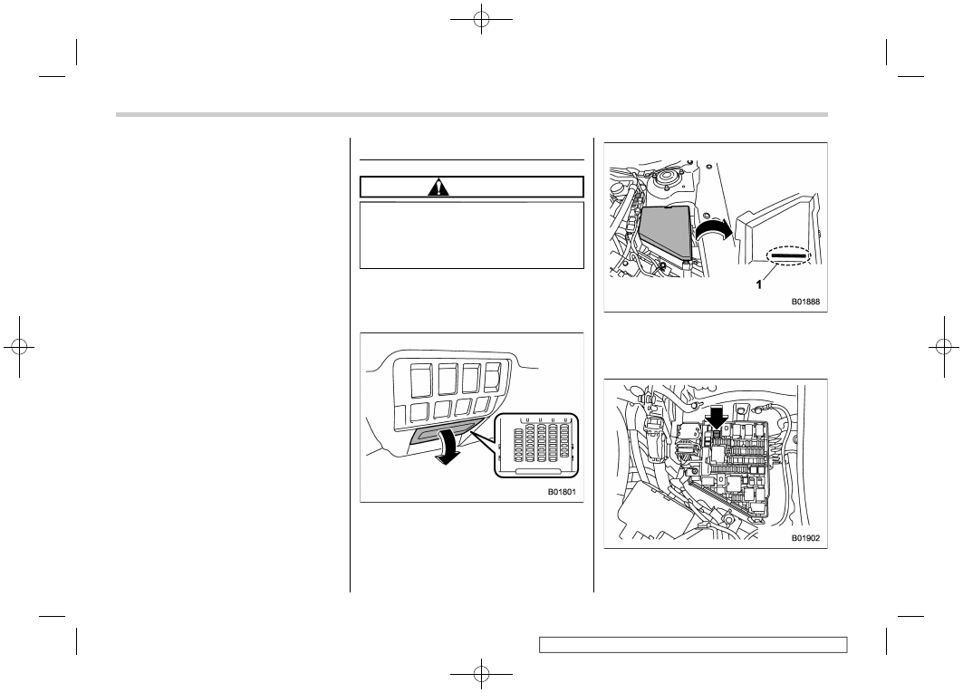
The fuses are designed to melt during an
overload to prevent damage to the wiring
harness and electrical equipment. The
fuses are located in two fuse boxes.

One is located under the instrument panel
behind the fuse box cover on the driver’s
seat side. To remove the cover, pull it out.

1)

Spare fuses

The other one (main fuse box) is housed in
the engine compartment. Also, the spare
fuses are stored in the fuse box cover.

The fuse puller is stored in the main fuse
box in the engine compartment.

Fuses

474

-------------------------------------------------------------------------------------------------------------------------------------------------------------

(477,1)

Pinch the upper part of the fuse puller
when removing it from the main fuse box.

1)

Good

2)

Blown

If any lights, accessories or other electrical
controls do not operate, inspect the corre-
sponding fuse. If a fuse has blown, replace
it.
1. Turn the ignition switch to the “LOCK”/
“OFF” position and turn off all electrical
accessories.
2. Remove the cover.
3. Determine which fuse may be blown.
Look at the back side of each fuse box
cover and refer to “Fuses and circuits”
FP495.

4. Pull out the fuse with the fuse puller.
5. Inspect the fuse. If it has blown,
replace it with a spare fuse of the same
rating.
6. If the same fuse blows again, this
indicates that its system has a problem.
Contact your SUBARU dealer for repairs.

11-23. Installation of acces-
sories

Always consult your SUBARU dealer
before installing fog lights or any other
electrical equipment in your vehicle. Such
accessories may cause the electronic
system to malfunction if they are incor-
rectly installed or if they are not suited for
the vehicle.

Installation of accessories

475

11

Maintenance

and

service

-------------------------------------------------------------------------------------------------------------------------------------------------------------

(478,1)

11-24. Replacing bulbs

It may be difficult to replace the bulbs. We
recommend that you have the bulb re-
placed by your SUBARU dealer if neces-
sary.

WARNING

Bulbs may become very hot while
illuminated. Before replacing bulbs,
turn off the lights and wait until the
bulbs cool down. Otherwise, there is
a risk of sustaining a burn.

CAUTION

.

Replace any bulb only with a new

bulb of the specified wattage.
Using a bulb of different wattage
could result in a fire. For the
specified wattage of each bulb,
refer to “Bulb chart” 
FP499.

.

Do not touch the glass portion of

the light bulb with bare hands.
When holding the glass portion is
unavoidable, hold it using with a
clean dry cloth to avoid getting
moisture and grease on the bulb.
If there is any fingerprints or
grease on the bulb surface, wipe

them away with a soft cloth
moistened with alcohol. Also, if
the bulb is scratched or dropped,
it may blow out or crack.

NOTE

For models with type B combination
meter, if SRH is malfunctioning, the
SRH OFF indicator appears on the
combination meter when the ignition
switch is in the “ON” position. It
indicates that SRH has been deacti-
vated. Contact a SUBARU dealer for an
inspection.

&

Headlights (models with LED
headlights)

The LED headlight warning light illumi-
nates if the LED headlights malfunction.
Have your vehicle inspected at a SUBARU
dealer as soon as possible.

Replacing bulbs

476

-------------------------------------------------------------------------------------------------------------------------------------------------------------

(479,1)

&

Front turn signal light

Right-hand side

1. Use a screwdriver to remove the clips
on the air intake duct, then remove the
duct.

Left-hand side

2. Use a screwdriver to remove the
secured clip of the washer tank. To make
it easy to access the bulb, turn the neck of
the washer fluid filler pipe as illustrated.

Type A

Type B

3. Disconnect the electrical connector
from the bulb and remove the bulb from
the headlight assembly by turning it
counterclockwise.

– CONTINUED –

Replacing bulbs

477

11

Maintenance

and

service

-------------------------------------------------------------------------------------------------------------------------------------------------------------

(480,1)

4. Replace the bulb. At this time, use care
not to touch the bulb surface.
5. To install the bulb to the headlight
assembly, turn it clockwise until it clicks.
6. Reconnect the electrical connector.
7. Put the air intake duct with the clips
(right-hand side).
8. Set the washer fluid filler pipe to the
original place and secure it with the clips
(left-hand side).

&

Front position light (if
equipped)

The bulbs of the front position lights are the
same as the front turn signal lights. Refer
to “Front turn signal light” FP477 for the
replacement order.

&

Front side marker light (if
equipped)

Right-hand side

1. Use a screwdriver to remove the clips
on the air intake duct, then remove the
duct.

Left-hand side

2. Use a screwdriver to remove the
secured clip of the washer tank. To make
it easy to access the bulb, turn the neck of
the washer fluid filler pipe as illustrated.

Replacing bulbs

478

-------------------------------------------------------------------------------------------------------------------------------------------------------------

(481,1)

3. Remove the bulb from the headlight
assembly by turning it counterclockwise.
4. Replace the bulb with a new one. At
this time, use care not to touch the bulb
surface.
5. To install the bulb to the headlight
assembly, turn it clockwise until it clicks.
6. Install the air intake duct with clips
(right-hand side).
7. Set the washer tank to the original
place and secure it with a clip (left-hand
side).

&

Front fog light (if equipped)

It may be difficult to replace the bulbs.
Have the bulbs replaced by your SUBARU
dealer if necessary.

&

Rear turn signal lights

1. Use a screwdriver to remove the
secured clips of the covers.

2. Push and move the cover to the
forward to unlock the 2 tabs.

3. When unlocked, pull out the covers.

– CONTINUED –

Replacing bulbs

479

11

Maintenance

and

service

-------------------------------------------------------------------------------------------------------------------------------------------------------------

(482,1)

4. Disconnect the electrical connector.

5. Using a Phillips screwdriver, remove
the screws that secure the rear combina-
tion light assembly.

6. Slide the rear combination light as-
sembly rearward to remove it from the
vehicle.

7. Remove the bulb socket from the rear
combination light assembly by turning it
counterclockwise.

8. Pull the bulb out of the bulb socket and
replace it.
9. Set the bulb socket into the rear
combination light assembly and turn it
clockwise until it locks.
10. Reconnect the electrical connector.

11. Put the rear combination light assem-
bly into place while aligning the 2 pins with
the holes and secure to the vehicle.

Replacing bulbs

480

-------------------------------------------------------------------------------------------------------------------------------------------------------------

(483,1)

12. Tighten the screws.
13. Put the covers back in place.

&

Backup light

1. Apply a flat-head screwdriver to the
light cover as shown in the illustration, and
pry the light cover off from the rear gate
trim.

2. Turn the bulb socket counterclockwise
and remove it.

3. Pull the bulb out of the bulb socket and
replace it.
4. Install the bulb socket by turning it
clockwise.

– CONTINUED –

Replacing bulbs

481

11

Maintenance

and

service

-------------------------------------------------------------------------------------------------------------------------------------------------------------


Content   ..  55  56  57  58   ..