Subaru Legacy IV (2008 year). Service manual - part 996
AC(diag)-36
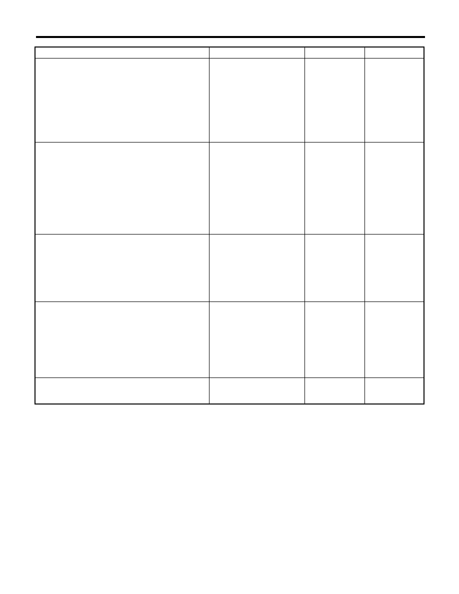
Diagnostic Procedure for Sensors
HVAC SYSTEM (AUTO A/C) (DIAGNOSTICS)
Step
Check
Yes
No
1
CHECK POWER SUPPLY VOLTAGE FOR
SUNLOAD SENSOR.
1) Turn the ignition switch to OFF.
2) Disconnect the connector from sunload
sensor.
3) Turn the ignition switch to ON.
4) Measure the power supply voltage for sun-
load sensor.
Connector & terminal
(i51) No. 1 (+) — No. 2 (–):
Is the voltage approx. 5 V?
Go to step 4.
Go to step 2.
2
CHECK HARNESS CONNECTOR BETWEEN
AUTO A/C CONTROL MODULE AND SUN-
LOAD SENSOR.
1) Turn the ignition switch to OFF.
2) Disconnect the connector from the auto A/C
control module.
3) Measure the resistance of the harness
between the auto A/C control module and sun-
load sensor.
Connector & terminal
(i51) No. 2 — (B282) No. 6:
Is the resistance less than 1
:? Go to step 3.
Repair the harness
between auto A/C
control module and
sunload sensor.
3
CHECK HARNESS CONNECTOR BETWEEN
AUTO A/C CONTROL MODULE AND SUN-
LOAD SENSOR.
Measure the resistance of the harness between
the auto A/C control module and sunload sen-
sor.
Connector & terminal
(i51) No. 1 — (B282) No. 8:
Is the resistance less than 1
:? Go to step 4.
Repair the harness
between auto A/C
control module and
sunload sensor.
4
CHECK INPUT VOLTAGE FOR AUTO A/C
CONTROL MODULE.
1) Connect the connectors of sunload sensor
and auto A/C control module.
2) Turn the ignition switch to ON.
3) Measure the voltage between connector
terminals of auto A/C control module.
Connector & terminal
(B282) No. 8 (+) — (B282) No. 6 (–):
Is the voltage approx. 2.5 V?
Go to step 5.
Replace the sun-
load sensor.
5
CHECK POOR CONTACT.
Check poor contact of auto A/C control module
connector.
Is there poor contact in connec-
tor?
Repair the connec-
tor.
Replace the auto
A/C control mod-
ule.