Subaru Legacy IV (2008 year). Service manual - part 773
5AT(diag)-107
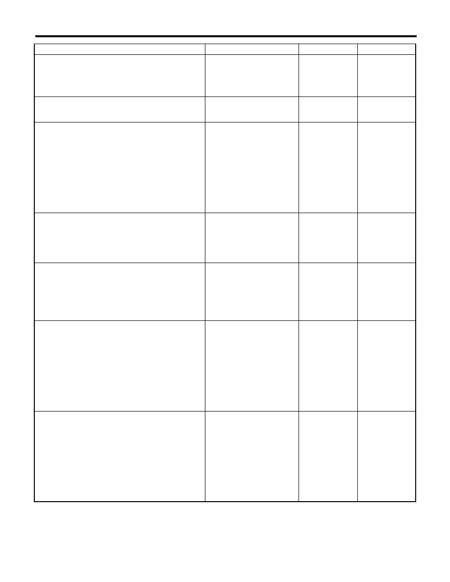
Diagnostic Procedure without Diagnostic Trouble Code (DTC)
AUTOMATIC TRANSMISSION (DIAGNOSTICS)
5
CHECK DTC OF TCM.
Is DTC of CAN detected?
Perform the diag-
nosis according to
DTC.
Replace the TCM.
<Ref. to 5AT-60,
Transmission Con-
trol Module
(TCM).>
6
CHECK DTC OF METER.
Is DTC of CAN detected?
Perform the diag-
nosis according to
DTC.
Replace the meter.
7
CHECK GROUND CIRCUIT OF SPORT/MAN-
UAL MODE SWITCH.
1) Turn the ignition switch to OFF.
2) Disconnect the connector from SPORT/
manual mode switch.
3) Measure the resistance of harness between
SPORT/manual mode switch connector and
chassis ground.
Connector & terminal
(B116) No. 6 — Chassis ground:
(B116) No. 10 — Chassis ground:
Is the resistance less than 1
:? Go to step 8.
Repair the open
circuit of harness
between SPORT/
manual mode
switch and chassis
ground.
8
CHECK SPORT/MANUAL MODE SWITCH.
Measure the resistance between SPORT/man-
ual mode switch terminals.
Connector & terminal
(B116) No. 6 — No. 7:
(B116) No. 10 — No. 11:
Is the resistance 1 M
: or
more?
Go to step 9.
Replace the guide
plate assembly.
9
CHECK SPORT/MANUAL MODE SWITCH.
1) Move the select lever to manual mode.
2) Measure the resistance between SPORT/
manual mode switch terminals.
Connector & terminal
(B116) No. 6 — No. 7:
(B116) No. 10 — No. 11:
Is the resistance less than 1
:? Go to step 10.
Replace the guide
plate assembly.
10
CHECK HARNESS CONNECTOR BETWEEN
BODY INTEGRATED UNIT AND SPORT/
MANUAL MODE SWITCH.
1) Disconnect the connector from body inte-
grated unit.
2) Measure the resistance of harness between
body integrated unit connector and SPORT/
manual mode switch connector.
Connector & terminal
(B116) No. 7 — (B281) No. 15:
(B116) No. 11 — (B281) No. 25:
Is the resistance less than 1
:? Go to step 11.
Repair the open
circuit of harness
between the
SPORT/manual
mode switch con-
nector and body
integrated unit con-
nector, or poor
contact of connec-
tor.
11
CHECK HARNESS CONNECTOR BETWEEN
BODY INTEGRATED UNIT AND SPORT/
MANUAL MODE SWITCH.
1) Disconnect the connector from body inte-
grated unit.
2) Measure the resistance of harness between
SPORT/manual mode switch connector and
chassis ground.
Connector & terminal
(B116) No. 7 — Chassis ground:
(B116) No. 9 — Chassis ground:
Is the resistance 1 M
: or
more?
Go to step 12.
Repair the short
circuit of harness
between SPORT/
manual mode
switch connector
and body inte-
grated unit connec-
tor.
Step
Check
Yes
No