Subaru Legacy IV (2008 year). Service manual - part 689


  Index      Subaru     Subaru Legacy IV - service and repair manual 2008 year


Search            


Content   ..  687  688  689  690   ..


Subaru Legacy IV (2008 year). Service manual - part 689


4AT-104

AT Main Case

AUTOMATIC TRANSMISSION

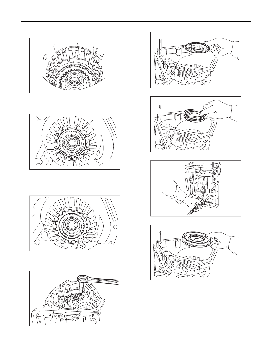
22) Pull out the leaf spring of the low & reverse
brake while being careful not to bend it.

23) Remove the snap ring.

24) Take out the retaining plate, drive plate, driven
plate and dish plate of the low & reverse brake.

25) Turn the transmission case upside down, and
then take out the socket bolts while holding the
one-way clutch inner race by hand.

26) Remove the spring retainer.

27) Take out the return spring.

28) Apply compressed air.

29) Take out the low & reverse brake piston.

(A) Leaf spring

(A) Snap ring

AT-00293

(A)

AT-00294

( A )

AT-00295

AT-00296

AT-00302

AT-00301

AT-04782

AT-00300

4AT-105

AT Main Case

AUTOMATIC TRANSMISSION

B: INSTALLATION

1) Install the low & reverse brake piston.

NOTE:
• Take care not to damage the lip seal.
• Apply ATF to the lip.

2) Install the return spring.

3) Install the spring retainer.

4) Install the one-way clutch inner race.
5) Tighten the socket head bolts evenly from the
rear side of transmission case.

Tightening torque:

25 N·m (2.5 kgf-m, 18.4 ft-lb)

6) Place the front side of transmission body up.
7) Install the thrust needle bearing.
8) Place the dish plate, driven plate, drive plate and
retaining plate neatly in this order on surface table.
9) Set the dial gauge to retaining plate, and read its
scale.

NOTE:
The value, which is read in the gauge at this time, is
zero point.
10) Scale and record the weight “Z” of the flat board
that will be placed on the retaining plate.

NOTE:
• Use a stiff board which does not bend against
load as a flat board to be put on retaining plate.
• Use a flat board weighing less than 8.5 kgf (18.7
lb).
11) Put the flat board on retaining plate.

12) Using the following formula, read the push/pull
gauge, and calculate “N”.
N = 83 N (8.5 kgf, 18.7 lb) – Z
N: Value indicated on push/pull gauge
83 N (8.5 kgf, 18.7 lb) : Load applied to clutch plate
Z: Flat board weight

AT-00300

AT-00301

AT-00302

AT-00296

AT-01720

4AT-106

AT Main Case

AUTOMATIC TRANSMISSION

13) Press the center of retaining plate with a force
of N using a push/pull gauge, and measure and
record height “A”. Measure at three or more loca-
tions spaced by equal distances and take the aver-
age value.

NOTE:
If measuring in three locations, measure every
120°. If measuring in four locations, measure every
90°.

14) Installation of the low & reverse brake:
Install the dish plate, driven plate, drive plate and
retaining plate, and then secure them with a snap
ring.

NOTE:
Pay attention to the orientation of the dish plate.

15) Apply compressed air intermittently to check for
operation.

16) Place same thickness shims on both sides to
prevent plate from tilting, then measure and record
the clearance “B”.

NOTE:
Do not push in the shim down with force to a point
where the waves on the drive plate will be crushed.

A Measured value

(A) Dish plate

(B) Drive plate

(C) Driven plate

(D) Retaining plate

AT-01721

(B)

(D)

(C)

(A)

A

(A) Snap ring

B Measured value

AT-00294

( A )

AT-04782

AT-02216

B

4AT-107

AT Main Case

AUTOMATIC TRANSMISSION

17) Piston stroke calculation
Calculate with A and B dimensions recorded be-
fore. If the calculated value exceeds the service
limit, replace the drive plate with a new part and ad-
just it within the initial specification.
T = A + B
T: Piston stroke
A: Amount of drive plate compression
B: Clearance between retaining plate and snap ring

Initial standard:

2.15 — 2.65 mm (0.085 — 0.104 in)

Limit thickness:

2.95 mm (0.116 in)

18) Install the leaf spring of the low & reverse
brake.

19) Install the 2-4 brake piston and 2-4 brake re-
tainer by aligning the hole of the 2-4 brake retainer
with the hole on the transmission case.

20) Install the 2-4 brake piston spring retainer to
the transmission case.

21) Position the snap ring in the transmission. Us-
ing ST, press the snap ring into the specified loca-
tion.
ST

498677100

COMPRESSOR

Retaining plate

Part No.

Thickness mm (in)

31667AA420

3.8 (0.150)

31667AA320

4.1 (0.161)

31667AA330

4.4 (0.173)

31667AA340

4.7 (0.185)

31667AA350

5.0 (0.197)

31667AA360

5.3 (0.209)

31667AA370

5.6 (0.220)

31667AA380

5.9 (0.232)

(A) Leaf spring

AT-00293

(A)

(A) 2-4 brake piston

(B) 2-4 brake piston retainer

AT-00287

(A)

(B)

AT-00286

AT-00289

S T


Content   ..  687  688  689  690   ..