Subaru Legacy IV (2008 year). Service manual - part 522
EN(H6DO)(diag)-61
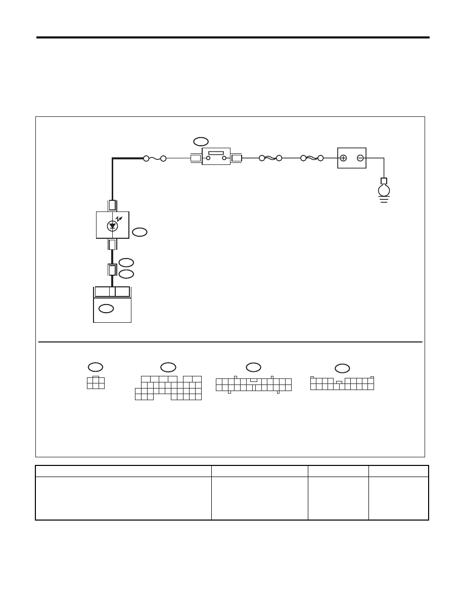
Malfunction Indicator Light
ENGINE (DIAGNOSTICS)
D: MALFUNCTION INDICATOR LIGHT DOES NOT GO OFF
DIAGNOSIS:
The malfunction indicator light circuit is shorted.
TROUBLE SYMPTOM:
Although malfunction indicator light comes on when the engine runs, DTC is not shown on the Subaru Select
Monitor display.
WIRING DIAGRAM:
Step
Check
Yes
No
1
CHECK HARNESS BETWEEN COMBINA-
TION METER AND ECM CONNECTOR.
1) Turn the ignition switch to OFF.
2) Disconnect the connectors from ECM.
3) Turn the ignition switch to ON.
Does the malfunction indicator
light illuminate?
Repair the short
circuit of harness
between combina-
tion meter and
ECM connector.
Replace the ECM.
<Ref. to
FU(H6DO)-38,
Engine Control
Module (ECM).>
1
3
4 5 6
2
1 2 3 4
5 6 7 8 9
10 11 12 13 14 15 16 17 18 19 20
2
1
3 4
6 7 8 9
22
21
20
19
18
17
16
15
14
13
12
11
5
16
10 11 12 13 14 15
25
24
30
9
8
7
17 18 19 20
28
21 22 23
29
32
31
1
2
3
4
5
6
27
26
33 34 35
SBF-6
MAIN SBF
3
1
B72
BATTERY
E
No.5
i10
3
i3
B38
8
16
B136
11
ECM
B72
B136
i10
B38
10
EN-05649
IGNITION
SWITCH
COMBINATION
METER