Subaru Legacy IV (2008 year). Service manual - part 462


  Index      Subaru     Subaru Legacy IV - service and repair manual 2008 year


Search            


Content   ..  460  461  462  463   ..


Subaru Legacy IV (2008 year). Service manual - part 462


FU(H6DO)-67

Fuel Delivery and Evaporation Lines

FUEL INJECTION (FUEL SYSTEMS)

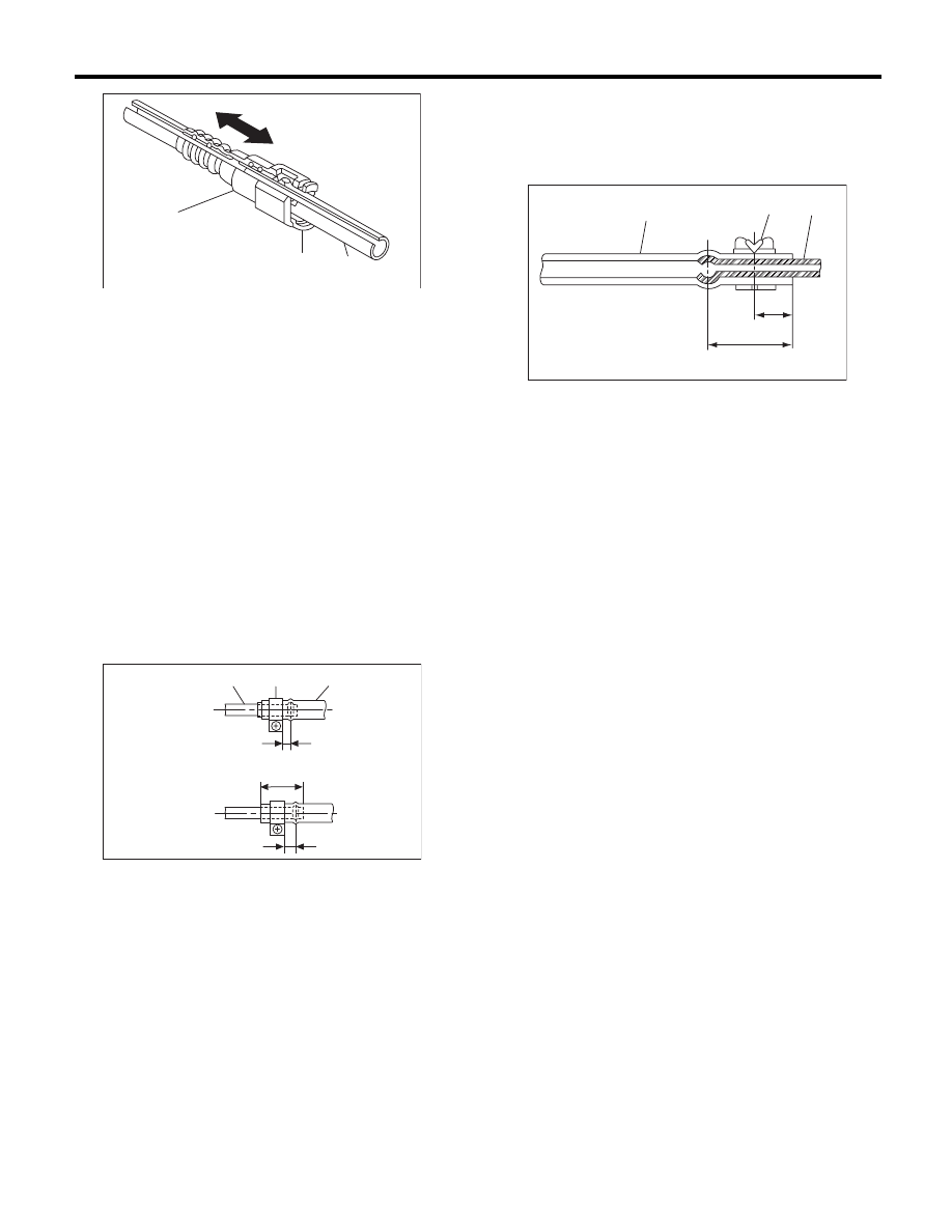
2. CONNECTING THE FUEL DELIVERY 
HOSE

Connect the fuel delivery hose to the pipe with an
overlap of 20 to 25 mm (0.79 to 0.98 in).
Type A: When the amount to be inserted is speci-
fied.
Type B: When the amount to be inserted is not
specified.

L1: 2.5

r

1.5 mm (0.098

r

0.059 in)

L2: 22.5

r

2.5 mm (0.886

r

0.098 in)

CAUTION:
Be sure to inspect hoses and their connections
for any leakage of fuel.

3. CONNECTING THE EVAPORATION HOSE

Connect the evaporation hose to the pipe with an
overlap of 15 to 20 mm (0.59 to 0.79 in).

L = 17.5

r

2.5 mm (0.689

r

0.098 in)

C: INSPECTION

1) Make sure that there are no cracks on the fuel
pipes and fuel hoses.
2) Make sure the fuel pipe and fuel hose connec-
tions are tightened firmly.

(A) Connector

(B) Retainer

(C) Pipe

(1) Type A

(2) Type B

(3) Pipe

(4) Clamp

(5) Hose

FU-00127

( A )

( B )

( C )

FU-03390

(3)

(4)

(5)

L2

(1)

(2)

L1

L1

(1) Hose

(2) Clip

(3) Pipe

FU-00129

(1)

(2)

L/2

L

(3)

FU(H6DO)-68

Fuel System Trouble in General

FUEL INJECTION (FUEL SYSTEMS)

33.Fuel System Trouble in General

A: INSPECTION

NOTE:
• When the vehicle is left unattended for an extended period of time, water may accumulate in the fuel tank.
Fill the fuel tank fully to prevent this.
• In snow-covered areas, mountainous areas, skiing areas, etc. where ambient temperatures drop to 0°C
(32°F) or less throughout the winter season, use a water removing agent in the fuel system to prevent freez-
ing fuel system and accumulating water.
• When water is accumulated in fuel filter, fill the water removing agent in the fuel tank.
• Before using water removing agent, follow the cautions noted on the bottle.

Trouble and possible cause

Corrective action

1. Insufficient fuel supply to injector

1)

Fuel pump does not operate.


Defective terminal contact

Inspect contact, especially ground, and tighten it 
securely.


Trouble in electromagnetic or electronic circuit parts

Replace the faulty parts.

2)

Decline of fuel pump function

Replace the fuel pump.

3)

Clogged fuel filter

Replace the fuel filter. Clean or replace the fuel tank if 
necessary.

4)

Clogged or bent fuel pipe or hose

Clean, correct or replace fuel pipe or hose.

5)

Air is mixed in the fuel system.

Inspect or retighten each connection part.

6)

Clogged or bent air breather tube or pipe

Clean, correct or replace the air breather tube or pipe.

7)

Damaged diaphragm of pressure regulator

Replace.

2. Leakage or blow out of fuel

1)

Loose joints of the fuel pipe

Retighten.

2)

Cracked fuel pipe, hose and fuel tank

Replace.

3)

Defective welding part on the fuel tank

Replace.

4)

Clogged or bent air breather tube or air vent tube

Clean, correct or replace the air breather tube or air vent 
tube.

3. Gasoline smell inside of compartment

1)

Loose joints at air breather tube, air vent tube and fuel filler 
pipe

Retighten.

2)

Problem in tightening of the fuel saucer gasket air

Correct or replace the gasket.

3)

Inoperative fuel pump modulator or circuit

Replace.

4. Defective fuel meter indicator

1)

Defective operation of fuel level sensor

Replace.

2)

Defective operation of fuel meter

Replace.

5. Noise

1)

Large operation noise or vibration of fuel pump

Replace.

EC(H6DO)-2

General Description

EMISSION CONTROL (AUX. EMISSION CONTROL DEVICES)

1. General Description

A: CAUTION

• Wear appropriate work clothing, including a cap,
protective goggles and protective shoes when per-
forming any work.
• Remove contamination including dirt and corro-
sion before removal, installation or disassembly.
• Keep the disassembled parts in order and pro-
tect them from dust and dirt.
• Before removal, installation or disassembly, be
sure to clarify the failure. Avoid unnecessary re-
moval, installation, disassembly and replacement.
• Vehicle components are extremely hot after driv-
ing. Be wary of receiving burns from heated parts.
• Be sure to tighten fasteners including bolts and
nuts to the specified torque.
• Place shop jacks or rigid racks at the specified
points.
• Before disconnecting connectors of sensors or
units, be sure to disconnect the ground cable from
battery.

EC(H6DO)-3

Front Catalytic Converter

EMISSION CONTROL (AUX. EMISSION CONTROL DEVICES)

2. Front Catalytic Converter

A: REMOVAL

The front and rear catalytic converters are integrat-
ed into the front exhaust pipe; therefore, refer to
“Front Exhaust Pipe” for the removal procedure.
<Ref. to EX(H6DO)-4, REMOVAL, Front Exhaust
Pipe.>

B: INSTALLATION

The front and rear catalytic converters are integrat-
ed into front exhaust pipe as one unit; therefore, re-
fer to “Front Exhaust Pipe” for installation
procedure. <Ref. to EX(H6DO)-5, INSTALLATION,
Front Exhaust Pipe.>

C: INSPECTION

1) Check the connections and welds for exhaust
leaks.
2) Check for hole or rust.

(A) Front catalytic converter

(B) Rear catalytic converter

(A) Front catalytic converter

(B) Rear catalytic converter

(A)

(B)

EC-02018

(A)

(B)

EC-02018


Content   ..  460  461  462  463   ..