Subaru Legacy IV (2008 year). Service manual - part 273


  Index      Subaru     Subaru Legacy IV - service and repair manual 2008 year


Search            


Content   ..  271  272  273  274   ..


Subaru Legacy IV (2008 year). Service manual - part 273


ME(H4DOTC)-72

Cylinder Head

MECHANICAL

4. INTAKE AND EXHAUST VALVE

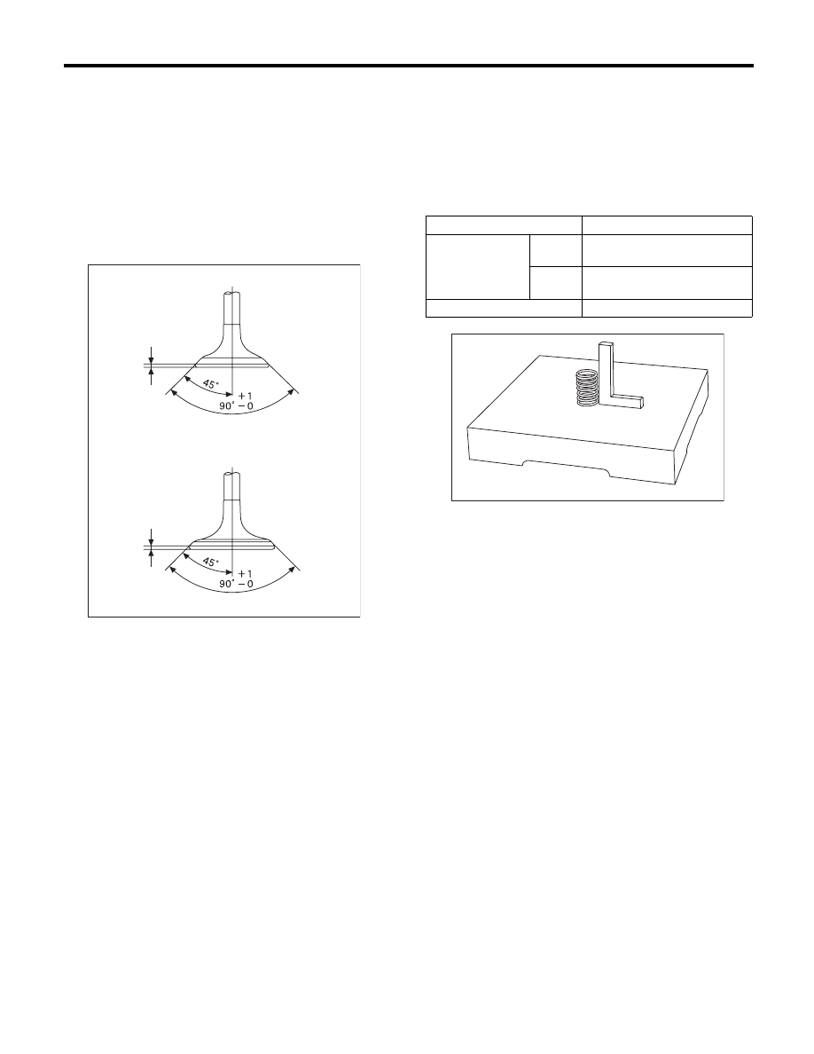
1) Inspect the flange and stem of valve, and re-
place the valve with a new part if damaged, worn,
deformed, or if “H” exceeds the specified limit.

Head edge thickness H:

Standard

Intake (A)

1.0 — 1.4 mm (0.039 — 0.055 in)

Exhaust (B)

1.3 — 1.7 mm (0.051 — 0.067 in)

2) Put a small amount of grinding compound on the
seat surface, and lap the valve and seat surface.
Replace with a new valve oil seal after lapping.

NOTE:
It is possible to differentiate between the intake
valve and the exhaust valve by their overall length.

Valve overall length:

Intake

104.4 mm (4.110 in)

Exhaust

104.65 mm (4.1201 in)

5. VALVE SPRING

1) Check the valve springs for damage, free length,
and tension. Replace the valve spring if it is not
within the standard value presented in the table.
2) To measure the squareness of the valve spring,
stand the valve spring on a surface plate and mea-
sure its deflection at the top of the spring using a try
square.

ME-00758

H

H

(B)

(A)

Free length

mm (in) 47.32 (1.863)

Tension/spring 
height
N (kgf, lbf)/mm (in)

Set

205 — 235 (20.9 — 24.0, 
46.1 — 52.8)/36.0 (1.417)

Lift

426 — 490 (43.4 — 50.0, 
95.8 — 110)/26.50 (1.041)

Squareness

2.5°, 2.1 mm (0.083 in) or less

ME-00283

ME(H4DOTC)-73

Cylinder Head

MECHANICAL

6. INTAKE AND EXHAUST VALVE OIL SEAL

1) For the following, replace the oil seal with a new
part. See the procedure 2) and subsequent for re-
placement procedures.
• When the lip is damaged.
• When the spring is out of the specified position.
• When readjusting the surfaces of valve and
valve seat.
• When replacing the valve guide.
2) Place the cylinder head on ST1, and use ST2 to
press-fit the oil seal.
ST1

498267600

CYLINDER HEAD TABLE

ST2

498857100

VALVE OIL SEAL GUIDE

NOTE:
• Apply engine oil to oil seal before press-fitting.
• When press-fitting the oil seal, do not use a ham-
mer, etc. or strike in.
• The intake valve oil seals and exhaust valve oil
seals are distinguished by their colors.

Color of rubber part:

Intake [Gray]
Exhaust [Green]

7. VALVE LIFTER

1) Check the valve lifter visually.
2) Measure the outer diameter of valve lifter.

Outer diameter:

34.959 — 34.975 mm (1.3763 — 1.3770 in)

3) Measure the inner diameter of valve lifter mating
surface on cylinder head.

Inner diameter:

34.994 — 35.016 mm (1.3777 — 1.3786 in)

NOTE:
If difference between outer diameter of valve lifter
and inner diameter of its mating surface is not with-
in the standard or there is uneven wear, replace the
cylinder head.

Standard:

0.019 — 0.057 mm (0.0007 — 0.0022 in)

ME-00133

ST2

ME-00134

ME-00135

ME(H4DOTC)-74

Cylinder Block

MECHANICAL

20.Cylinder Block

A: REMOVAL

NOTE:
Before conducting this procedure, drain the engine
oil completely.
1) Remove the V-belts. <Ref. to ME(H4DOTC)-41,
REMOVAL, V-belt.>
2) Remove the intake manifold. <Ref. to
FU(H4DOTC)-16, REMOVAL, Intake Manifold.>
3) Remove the crank pulley. <Ref. to
ME(H4DOTC)-44, REMOVAL, Crank Pulley.>
4) Remove the timing belt cover. <Ref. to
ME(H4DOTC)-46, REMOVAL, Timing Belt Cover.>
5) Remove the timing belt. <Ref. to ME(H4DOTC)-
47, REMOVAL, Timing Belt.>
6) Remove the cam sprocket. <Ref. to
ME(H4DOTC)-56, REMOVAL, Cam Sprocket.>
7) Remove the crank sprocket. <Ref. to
ME(H4DOTC)-57, REMOVAL, Crank Sprocket.>
8) Remove the generator and A/C compressor with
their brackets.
9) Remove the camshaft. <Ref. to ME(H4DOTC)-
58, REMOVAL, Camshaft.>
10) Remove the cylinder head. <Ref. to
ME(H4DOTC)-64, REMOVAL, Cylinder Head.>
11) Remove the clutch disc and cover. (MT model)
<Ref. to CL-13, REMOVAL, Clutch Disc and Cov-
er.>
12) Remove the flywheel. (MT model) <Ref. to CL-
16, REMOVAL, Flywheel.>
13) Use the ST to lock the crankshaft, and remove
the drive plate. (AT model)
ST

498497100

CRANKSHAFT STOPPER

14) Remove the oil separator cover.
15) Remove the water by-pass pipe for heater.
16) Remove the oil filter. <Ref. to LU(H4SO)-23,
REMOVAL, Engine Oil Filter.>
17) Remove the oil cooler. <Ref. to LU(H4SO)-22,
REMOVAL, Engine Oil Cooler.>
18) Remove the water pump. <Ref. to
CO(H4DOTC)-16, REMOVAL, Water Pump.>

19) Remove the bolts which install oil pump onto
cylinder block.

NOTE:
When disassembling and checking the oil pump,
loosen the relief valve plug before removing the oil
pump.

20) Remove the oil pump from cylinder block using
a flat tip screwdriver.

CAUTION:
Be careful not to scratch the mating surface of
cylinder block and oil pump.

21) Remove the front oil seal from the oil pump.
22) Remove the oil pan.

(1) Set the part so that the cylinder block LH is
on the upper side.
(2) Remove the bolts which secure oil pan to
cylinder block.
(3) Insert an oil pan cutter blade between cylin-
der block-to-oil pan clearance and remove the
oil pan.

CAUTION:
Do not use a screwdriver or similar tools in
place of oil pan cutter.
23) Remove the oil strainer.
24) Remove the baffle plate.
25) Remove the water tank pipe assembly.

ME-00136

ST

LU-00015

ME-00138

ME(H4DOTC)-75

Cylinder Block

MECHANICAL

26) Remove the water pipe assembly.

ME-00300

(1)

Service hole plug

(4)

Piston pin

(7)

Seal washer

(2)

Gasket

(5)

Service hole cover

(8)

Washer

(3)

Snap ring

(6)

O-ring


ME-02889

(3)

(4)

(2)

(1)

(3)

(4)

(5)

(6)

(2)

(3)

(2)

(1)

(3)

(4)

(4)

(8)

(7)

(1)


Content   ..  271  272  273  274   ..