Content .. 1132 1133 1134 1135 ..
Subaru Legacy IV (2008 year). Service manual - part 1134
EI-35
Front Bumper
EXTERIOR/INTERIOR TRIM
9
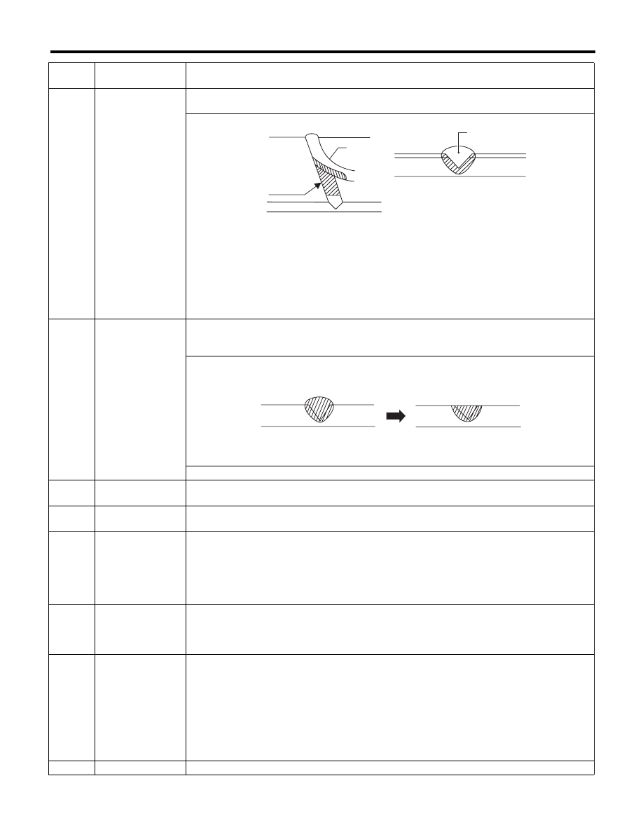
Welding
Using a heater gun and PP welding rod, weld the beveled spot while melting both the rod and
damaged area.
(1) Welding rod
(2) Melt hatched area
(3) Section
NOTE:
• Melt the sections indicated by hatched area.
• Do not melt the welding rod until it flows out, in order to provide strength.
• Always keep the heater gun 1 to 2 cm (0.4 to 0.8 in) away from the welding spot.
• Leave the welded spot unattended until it cools completely.
10
Sanding (II)
Remove excess part of weld with a putty knife. If a drill or disc wheel is used instead of the knife,
operate it at a rate lower than 1,500 rpm and grind the excess part little by little. A higher rpm will
cause the PP substrate to melt from the heat.
Sand the welded spot smooth with #240 sand paper.
11
Masking
Mask the black substrate section using masking tape.
Recommended masking tape: Nichiban No. 533 or equivalent
12
Cleaning/degreas-
ing
Completely clean the entire coated area, using solvent similar to that used in procedure No. 4.
13
Primer coating
Apply a coat of primer to the repaired surface and its surrounding areas. Mask these areas, if
necessary.
Recommended primer: Mp/ 364 PP Primer
NOTE:
Be sure to apply a coat of primer using a spray gun at a pressure of 245 — 343 kPa (2.5 — 3.5 kg/cm
2
,
36 — 50 psi).
14
Leave unattended
Leave the repaired area unattended at 20°C (68°F) for 10 to 15 minutes until primer is half-dry.
NOTE:
If dirt or dust comes in contact with the coated area, wipe it off with a cloth dampened with alcohol.
(Do not use thinner since the coated area tends to melt.)
15
Primer surfacer
coating
Apply primer surfacer to the repaired area two or three times at an interval of 3 — 5 minutes.
• Recommended surfacer:
UPS 300 Flex Primer
No. 303 UPS 300 Exclusive hardener
NPS 725 Exclusive Reducer (thinner)
• Mixture ratio:
2 : 1 (UPS 300 : No. 303)
• Viscosity: 12 — 14 seconds/20°C (68°F)
• Coating film thickness: 40 — 50 μ
16
Drying
Allow the coated surface to dry for 20 minutes at 20°C (68°F) [or 30 minutes at 60°C (140°F)].
Process
No.
Process name
Job contents
(1)
(2)
(2)
(3)
EI-00237
EI-00042