Subaru Legacy IV (2008 year). Service manual - part 14


  Index      Subaru     Subaru Legacy IV - service and repair manual 2008 year


Search            


Content   ..  12  13  14  15   ..


Subaru Legacy IV (2008 year). Service manual - part 14


PI-13

Pre-delivery Inspection

PRE-DELIVERY INSPECTION

22.ALARM SYSTEM

NOTE:
The following inspections show the initial settings.
When the settings are different from the initial set-
tings, use Subaru Select Monitor to check the de-
tails of each setting for inspections. <Ref. to
LAN(diag)-30, OPERATION, Function Setting
(Customize).>
1) Fully open all the door windows.
2) Remove the key from the ignition switch and
close all the doors including rear gate.
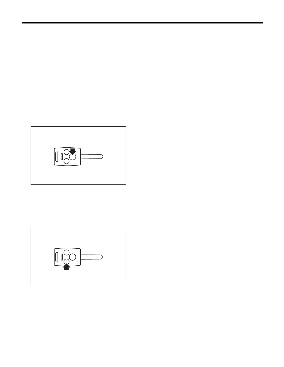
3) Press the “LOCK” button momentarily on the
keyless transmitter. All doors are locked, and buzz-
er sounds once, hazard blinks once, security indi-
cator light blinks faster (five times per two seconds)
for 30 seconds and goes slower (twice per two sec-
onds), then the alarm system is in set condition.

4) Press the “UNLOCK” button momentarily on the
keyless transmitter. When the door of the driver’s
seat is unlocked, the buzzer sounds twice, the haz-
ard light flashes twice, the room light turns on and
the security indicator light flashes once in three
seconds, and the alarm system enters the release
mode.

5) Close all the doors including rear gate. Press the
“LOCK” button momentarily on the keyless trans-
mitter. When all the doors are locked, buzzer
sounds once, hazard blinks once and the alarm
system is in set condition in 30 seconds.

6) Unlock a door using the inner lock knob and
open the door while the security system is in the set
mode. Check if the alarm condition happens (horn
sounds continuously, hazard light blinks, security
indicator illuminates). Check if this condition lasts
for a maximum of three minutes or until the “UN-
LOCK” button of the keyless transmitter is pressed.

NOTE:
The alarm condition will cease in 30 seconds once
the door is closed.
7) When none of above is applicable, check the
troubleshooting of security system.

PI-00387

PI-00388

PI-14

Pre-delivery Inspection

PRE-DELIVERY INSPECTION

23.SEAT

1) Check the seat surfaces for stains or dirt.
2) Check that each seat provides full functionality in
sliding and reclining. Check that the seat position
memory for driver’s power seat function properly.
Check all available functions of the rear seat such
as a trunk-through center armrest.
3) Check that the passenger’s seat occupant de-
tection system.

(1) Turn the ignition switch to ON.
(2) Check that the ON and OFF of passenger’s
airbag indicator light come on simultaneously
for about 6 seconds and go off for 2 seconds,
and then only OFF illuminates again.

(3) Have a person weighing approximately 70
kg (155 lb) or more sit in the passenger’s seat,
and check whether the passenger’s airbag indi-
cator light illuminate or not.
(4) Empty the passenger seat, then check
whether the passenger side airbag indicator
light OFF illuminates.

24.SEAT BELT

1) Check installation condition of seat belt.
2) Pull out the seat belt and then release it. Check
that the belt retracts smoothly.
3) Check that the ALR seat belt operates normally.
4) Check seat belt warning system

(1) Turn the ignition switch to ON without fas-
tening driver’s and passenger’s seat belts.
(2) Check if the seat belt warning lights of driv-
er’s and passenger’s side blink for about six
seconds and the buzzer beeps intermittently.
(3) Then, check that the seat belt warning light
comes on 

o blink in about 15 second cycles. (If

the passenger seat is empty, the seat belt warn-
ing light for passenger’s side does not operate.)

25.DELIVERY (TEST) MODE CONNECTOR

Turn the ignition switch to ON and check that the
malfunction indicator light starts blinking. If the light
blinks, return the ignition key to LOCK. Pull out the
test mode connector from the back of glove box
lower cover, and disconnect the test mode connec-
tor. Then, turn the ignition key to ON again. If the
malfunction indicator light blinks at that time in spite
of the disconnected delivery test mode connector,
carry out an engine diagnosis.

26.IMMOBILIZER SYSTEM

1) Check that the engine starts with all keys that
are equipped on vehicle.
2) 60 seconds after turning ignition switch from ON
to ACC or OFF, or immediately after removing the
key, check that the security indicator light blinking.

NOTE:
If malfunctions occur, refer to “IMMOBILIZER (DI-
AGNOSIS)”.

27.STARTING CONDITION

Start the engine and check that the engine starts
smoothly. If the battery voltage is low, recharge or
replace the battery. If any noises are observed, im-
mediately stop the engine and check and repair the
abnormal components.

28.EXHAUST SYSTEM

Listen to the exhaust noise to see if no noises are
observed. Check for exhaust leaks.

29.INDICATOR AND WARNING LIGHTS

Check that all indicator lights and warning lights op-
erate normally.

30.HEATER & VENTILATION

Operate the heater & ventilation system to check
for normal airflow outlet control, air inlet control, air-
flow capacity and heating performance.

OD-00036

(A) Delivery (test) mode connector

PI-00201

(A)

PI-15

Pre-delivery Inspection

PRE-DELIVERY INSPECTION

31.AIR CONDITIONER

Operate the air conditioner. Check that the A/C
compressor operates normally and enough cooling
is provided.

NOTE:
To prevent the insufficient lubrication of air condi-
tioner, operate the air conditioner for 5 minutes at
idling.

32.CLOCK

Check the clock for normal operations and enough
accuracy.

33.AUDIO

Check the radio for full functionality and normal
noise level. Check the CD unit operations.

34.NAVIGATION SYSTEM

1) Check all display functions for normal operation.
2) Check the map disc (DVD) are provided on vehi-
cle.
3) Check that the navigation system operates nor-
mally.

35.FRONT ACCESSORY POWER SUPPLY 
SOCKET

1) Check the operation of the front accessory pow-
er supply socket.
2) Check operation of the accessory power supply
socket in console box.

36.LIGHTING SYSTEM

1) Check the headlight operations.
2) Check the stop light operation.
3) Check other lights for normal operations.

37.WIPER DEICER

Check that the wiper deicer operates normally.

38.ILLUMINATION CONTROL

Check that the illumination control operates nor-
mally.

39.WINDOW WASHER

Check that the window washer system injects
washer fluid to the specified area of the windshield
shown in the figure.

Front injection position:

A: 250 mm (9.84 in)
B: 535 mm (21.1 in)

Rear injection position:

Wagon model
A: 70 mm (2.8 in)
B: 70°

40.WIPER

Check the front and rear wipers for normal opera-
tions.

41.POWER WINDOW

Operate the power window switches one by one to
check that each of the power windows goes up and
down without noises.

42.SUNROOF

Check that the sunroof operates normally.

43.DOOR MIRROR

Check that the remote control mirror operates nor-
mally.

44.BRAKE TEST

Check the foot brake for normal operations.

(1) Nozzle

(2) Spray area (shaded area)

A

A

(1)

(2)

B

WW-00395

A

B

PI-00104

PI-16

Pre-delivery Inspection

PRE-DELIVERY INSPECTION

45.PARKING BRAKE

Check the parking brake for normal operations.
When pulling the parking brake lever with force of
200 N (20.4 kgf, 45.0 lb), check that the lever stroke
of parking brake lever is 5 to 6 notches.

46.AT SHIFT CONTROL

1) Turn the ignition switch to ON.
2) While brake pedal is not depressed, check if the
select lever does not move from “P” range.
3) While brake pedal is depressed, check if the se-
lect lever moves from “P” range.
4) Set the select lever to other than “P” range.
5) When the ignition switch is turned to OFF, check
if the ignition key switch cannot be removed.
6) Set the AT selector lever to each gear position
and check the shifting while driving the vehicle.

• 4AT

• 5AT

47.CRUISE CONTROL

Operate the cruise control system. Check that the
system is activated and deactivated correctly.

48.ATF LEVEL

After selecting all positions (P, R, N, D), set the se-
lect lever in “P” range. Idle the engine for 1 or 2 min-
utes, and measure the ATF level. If the amount is
insufficient, check that no leaks are found. Then,
add the necessary amount of the specified ATF.
• 4AT

• 5AT

Selector position

Gear position

1st

2nd

3rd

4th

D

OK

OK

OK

OK

Manual mode

OK

OK

OK

OK

Selector position

Gear position

1st

2nd

3rd

4th

5th

D

OK

OK

OK

OK

OK

Manual mode

OK

OK

OK

OK

OK

PI-00199

P

R

N

D

(A) Level gauge

(B) ATF level range at “HOT” 

[70 — 80°C (158 — 176°F)]

(C) Upper level

(D) Lower level

(E) ATF level range at “COLD” 

[20 — 30°C (68 — 86°F)]

(A) Level gauge

(B) ATF level range at “HOT” 

[70 — 80°C (158 — 176°F)]

(C) Upper level

(D) Lower level

(E) ATF level range at “COLD” 

[20 — 30°C (68 — 86°F)]

COLD

LF

HOT

LF

(A)

(C)

(D)

(C)

(D)

(E)

(B)

PI-00521

(A)

PI-00362

COLD

LF

HOT

LF

(A)

(B)

(D)

(E)

(D)

(C)

(C)


Content   ..  12  13  14  15   ..