Subaru Legacy (2005 year). Service manual - part 856
PS-95
POWER ASSISTED SYSTEM (POWER STEERING)
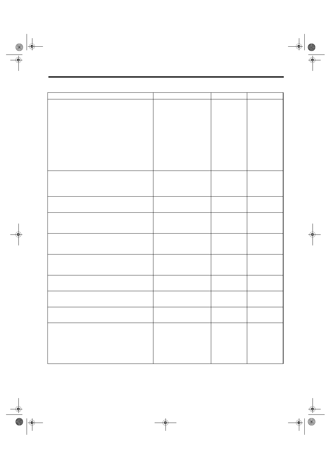
General Diagnostic Table
2. MEASUREMENT OF STEERING EFFORT
Step
Check
Yes
No
1
CHECK STEERING EFFORT.
1) Stop the vehicle on a concrete road.
2) Start the engine.
3) Run the engine at idle.
4) Install a spring scale on the steering wheel.
5) Pull the spring scale at a right angle to the
steering wheel, and measure both right and left
steering wheel efforts.
NOTE:
When turning the steering more quickly than
necessary from a direction to the other direction
at an engine speed over 2,000 rpm, steering ef-
fort may be heavy. This is caused by flow char-
acteristic of oil pump and is not defective.
Is the steering effort less than
29.4 N (3.0 kgf, 6.6 lbf)?
Adjust the back-
lash.
2
CHECK STEERING EFFORT.
1) Stop the engine.
2) Pull the spring scale at a right angle to the
steering wheel, and measure both right and left
steering wheel efforts.
Is the steering effort less than
294.2 N (30 kgf, 66.2 lbf)?
Perform adjust-
ment.
3
CHECK STEERING WHEEL EFFORT.
1) Remove the universal joint.
2) Measure steering wheel effort.
Is the steering effort less than
2.26 N (0.23 kgf, 0.51 lbf)?
Check, adjust and
replace if neces-
sary.
4
CHECK STEERING WHEEL EFFORT.
Measure steering wheel effort.
Is the difference of steering
effort between clockwise and
counterclockwise less than
20%?
Check, adjust and
replace if neces-
sary.
5
CHECK UNIVERSAL JOINT.
Measure the swing torque of the joint (yoke of
steering column side). <Ref. to PS-22,
INSPECTION, Universal Joint.>
Is the swing torque of universal
joint less than 7.3 N (0.74 kgf,
1.64 lbf)?
Replace with a
new one.
6
CHECK UNIVERSAL JOINT.
Measure the swing torque of the joint (yoke of
gearbox side). <Ref. to PS-22, INSPECTION,
Universal Joint.>
Is the swing torque of universal
joint less than 3.8 N (0.39 kgf,
0.86 lbf)?
Replace with a
new one.
7
CHECK FRONT WHEEL.
Check the front wheel.
If the front wheels have
unsteady revolution or rattling
and brake for dragging?
Inspect, readjust
and replace if nec-
essary.
8
CHECK TIE-ROD ENDS.
Remove the tie-rod ends.
If the tie-rod ends of suspen-
sion have unsteady revolution
or rattling?
Inspect and
replace if neces-
sary.
9
CHECK BALL JOINT.
Remove the ball joint.
If the ball joints of suspension
have unsteady revolution or
rattling?
Inspect and
replace if neces-
sary.
10
CHECK GEARBOX.
Measure the rotating of gearbox.
<Ref. to PS-44, TURNING RESISTANCE OF
GEARBOX, INSPECTION, Steering Gearbox
[LHD Model].> or <Ref. to PS-63, TURNING
RESISTANCE OF GEARBOX, INSPECTION,
Steering Gearbox [RHD Model].>
Is the rotating resistance of
steering gearbox less than
LHD model: 10.5 N (1.1 kgf,
2.4 lbf) or RHD model: 13 N
(1.3 kgf, 2.9 lbf)? Is the differ-
ence between clockwise and
counterclockwise less than
20%?
Readjust the back-
lash, and if ineffec-
tive, replace the
faulty parts.