SsangYong Rexton. Service manual - part 624


  Index      SsangYong     SsangYong Rexton - service and repair manual


Search            


Content   ..  622  623  624  625   ..


SsangYong Rexton. Service manual - part 624


SSANGYONG  Y200

7A-16  HEATING AND VENTILATION SYSTEM

6. Installation should follow the removal procedure

in the reverse order.

Install the nozzle and the ventilation duct to the
instrument panel.

Install the duct at console side with air duct.
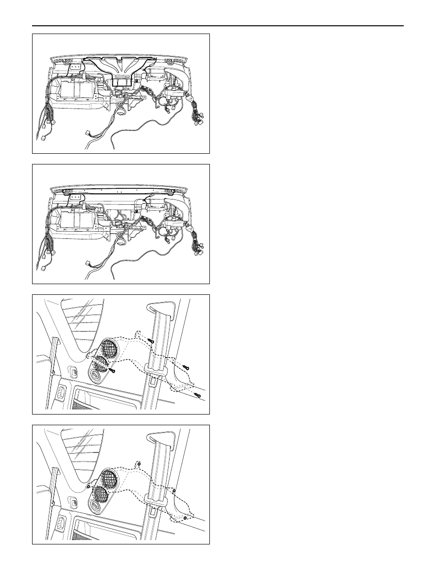
REAR COOLER DUCT

Removal & Installation Procedure

1. Remove the rear quarter inner panel.

2. Remove the tapping screw and hex screw at the

duct.

3. Remove the duct.

4. Installation should follow the removal procedure

in the reverse order.

YAD7A090

YAD7A100

YAD7A110

YAD7A120

HEATING AND VENTILATION SYSTEM  7A-17

SSANGYONG  Y200

HEATER AND BLOWER MODULE
ASSEMBLY

Removal & Installation Procedure

1. Disconnect the blower motor connecter.

2. Remove the retaining bolts of the blower module

and evaporator and then remove the blower
module.

Notice: A/C pipe should be removed previously.

3. Remove the heater module retaining bolts and

heater module assembly.

Notice:  Note that it is possible to remove the
heater module only when you remove the heater
hose previously.

4. Installation should follow the removal procedure

in the reverse order.

Tighten the heater module with the retaining
bolts.

Retaining Bolt

5 N•m (44 lb-in)

YAD7A130

YAD7A140

YAD7A150

YAD7A160

SSANGYONG  Y200

7A-18  HEATING AND VENTILATION SYSTEM

Tighten the blower module assembly with
retaining nuts.

Connect the blower motor connector and install
the heater hose and A/C pipe.

HEATER SUCTION AND
DISCHARGE HOSE

Removal & Installation Procedure

1. Drain the coolant.

2. Remove the clips and push back the suction

heater hose clamp near the fire wall.

3. Twist the hose slowly from the left side to the right

side to loosen the connection between the hose
and the tube.

4. Remove the hose end from the tube.

5. Remove the clip and push back the heater suction

hose at engine block side.

6. Remove the heater suction hose and discharge

hose on the vehicle.

7. Installation should follow the removal procedure

in the reverse order.

Retaining Bolt

5 N•m (44 lb-in)

YAD7A170

YAD7A180

YAD7A190

YAD7A200

SECTION 7B

GENERAL HVAC (HEATING, VENTILATION

AND AIR CONDITIONING) SYSTEM

TABLE OF CONTENTS

Description and Operation ................................... 7B-2

Specifications ...................................................... 7B-2

Repair Instructions ............................................... 7B-3

Basic A/C System Function .................................. 7B-5

Component Locator ............................................. 7B-7

A/C System Component ...................................... 7B-7

A/C System Pipe Line .......................................... 7B-8

Compressor Location ........................................... 7B-9

Diagnostic Information and Procedures ............ 7B-10

General Diagnosis ............................................. 7B-10

Diagnosis Using The Manifold Gauge ................ 7B-11

Maintenance and Repair ................................... 7B-13

Refrigerant Charging .......................................... 7B-13

Compressor Oil Replacement ............................ 7B-17

Replacement of Refrigerant Connection .............. 7B-18

Repair Instructions .............................................. 7B-19

On-Vehicle Service ............................................... 7B-19

Air Filter (Auto A/C) ............................................ 7B-19

Receiver-Dryer ................................................... 7B-20

Condenser ......................................................... 7B-21

Compressor ....................................................... 7B-23

A/C High/Low Pressure Line ............................... 7B-23

A/C Module Assembly ....................................... 7B-24

Unit Repair ........................................................... 7B-25

Compressor ....................................................... 7B-25

Special Tools and Equipment ............................ 7B-27

Special Tools Table ............................................ 7B-27


Content   ..  622  623  624  625   ..