SsangYong Rexton. Service manual - part 556


  Index      SsangYong     SsangYong Rexton - service and repair manual


Search            


Content   ..  554  555  556  557   ..


SsangYong Rexton. Service manual - part 556


AUTOMATIC TRANSMISSION  5A-199

SSANGYONG  Y200

KAA5A2B0

KAA5A2A0

KAA5A510

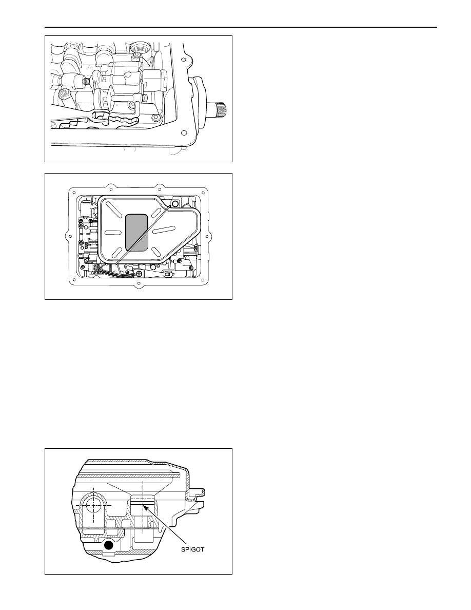
2. Carefully assemble the oil filter to the valve body.

The spigot must not lean on one side while being
fitted.

3. Secure the oil filter assembly with the retainer.

4. Check that the magnet is located in the dimple in

the corner of the oil pan.

5. Assemble the gasket on the pan lip. The gasket

must be free of any distortion when installed.

25. Check the alignment of the detent roller and the

manual lever quadrant.

26. Connect the solenoid wiring as detailed below:

Solenoid 1 - red

Solenoid 2 - bIue

Solenoid 3 - yellow

Solenoid 4 - orange

Solenoid 5 - green

Solenoid 6 - violet

Notice: All hardware must be correctly installed and
torqued to specification.

Oil Filter and Pan Assembly

Notice:

Replace the filter whenever rebuilding a
transmission where a significant amount of
mechanical damage has occurred.

To aid the assembly of the pan gasket, use a small
amount of Vaseline at the pan/gasket interface. This
ensures that the gasket remains on the pan ridge.
Do not over torque pan bolts as this may distort
the pan and cause leaks.

Ensure that the internal line pressure plus in the
valve body is fitted.

1. Lubricate the oil filter sealing ring with automatic

transmission fluid.

5A-200  AUTOMATIC TRANSMISSION

SSANGYONG  Y200

KAC5A040

KAA5A2D0

KAC5A040

Torque Converter and Housing Assembly

1. Locate the torque converter housing on the trans-

mission main case.

2. Apply additional Loctite 202 or equivalent as

required to the converter housing to case bolts.
Install and tighten bolts to specification.

Installation Notice

All the hardware must be correctly installed and
torqued to specification.

3. Fit the converter ensuring that the tangs are

engaged in the pump gear. Ensure that the tangs
do not contact the pump seal.

Output Flange Assembly (2WD Mode)

1. Position the transmission detent lever into the park

position and lock the output shaft.

2. Clear the threads on the output shaft and apply

Loctite 243 or equivalent as required to threads.

3. Install the flange, ‘O’ ring and torque the nut to

specification.

Installation Notice

Tightening Torque

35 N•m (26 lb-ft)

KAA5A2C0

6. Fit the oil pan assembly to the transmission case

and tighten the securing bolts to specification and
sequence Do not over torque.

Installation Notice

Tightening Torque

4-6 N•m (35-53 lb-in)

Tightening Torque

54-68 N•m (40-50 lb-ft)

AUTOMATIC TRANSMISSION  5A-201

SSANGYONG  Y200

1. Measure the projection of the front servo push rod

from the transmission case dimension ’A’.

a. Apply air at 650/700 kPa to the front servo apply

area (B1 outer)

b. Measure the travel of the push rod and subtract

3 mm to find the shim size required.

c. Release the air.

Notice: A minimum of one shim is required at all times
- minimum shim size is 1 mm. The thickness of
available shims are listed in the table below.

FRONT AND REAR BAND ADJUSTMENT

Front Band Setting Procedure

2. Fit the selected shim(s) to the shank of the anchor

strut as follows:

a. Inspect the shim(s) for damage, wear or corro-

sion. Replace as necessary.

b. The shim(s) are to be installed between the case

abutment face and the anchor strut flange.

c. The shim(s) are to be fitted by hand and under

no circumstances to be hammered or forced.

d. Shim(s) are to be pressed on by hand until an

audible click is heard. The click indicates that
the shim is clipped home correctly.

3. Re-check that the push rod travel. (3mm ±0.25mm)

KAA5A2E0

Thickness(mm)

Part Number

0.95/1.05

0574-037017

1.15/1.25

0574-037018

1.44/1.56

0574-037019

1.73/1.87

0574-037020

1.93/2.07

0574-037021

2.12/2.28

0574-037022

2.42/2.58

0574-037023

2.61/2.79

0574-037024

5A-202  AUTOMATIC TRANSMISSION

SSANGYONG  Y200

1. Measure distance‘A’ from the rear servo piston to

the inner face of the transmission case using vernier
calipers.

a. Apply air at 650/700 kPa to the rear servo apply

area (B2 outer)

b. Measure the travel of the piston, subtract 3.75

mm and divide the remainder by 2.5 to find shim
size.

c. Release the air.

Notice: A minimum of one shim is required at all times
- minimum shim size is 1 mm. The thickness of
available shims are listed in the table below.

Rear Band Setting Procedure

2. Fit the selected shim(s) to the shank of the anchor

strut as follows.

a. Inspect the shim(s) for damage, wear or

corrosion and replace as necessary. The shim(s)
are to be installed between the case abutment
face and the anchor strut flange.

b. The shim(s) are to be fitted by hand and under

no circumstances to be hammered or forced

c. The shim(s) are to be pressed on by hand until

an  audible click is heard. The click indicates
that the shim is clipped home correctly.

3. Re-check that the piston travel.

(3.75 mm ± 0.625 mm)

KAA5A2F0

Thickness(mm)

Part Number

0.0.95/1.05

0574-037017

1.15/1.25

0574-037018

1.44/1.56

0574-037019

1.73/1.87

0574-037020

1.93/2.07

0574-037021

2.12/2.28

0574-037022

2.42/2.58

0574-037023

2.61/2.79

0574-037024


Content   ..  554  555  556  557   ..