SsangYong Rexton. Service manual - part 550


  Index      SsangYong     SsangYong Rexton - service and repair manual


Search            


Content   ..  548  549  550  551   ..


SsangYong Rexton. Service manual - part 550


AUTOMATIC TRANSMISSION  5A-175

SSANGYONG  Y200

KAA5A920

KAA5A600

KAA5A930

KAA5A580

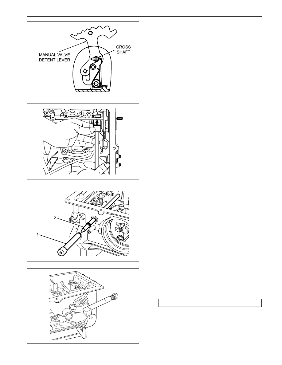
11. Poition the manual valve detent lever, aligning it

with the cross-shaft bore in the case.

12. Push the shaft through the detent lever until it starts

in the detent lever side of the case.

16. Install the new cross shaft seals using cross shaft

seal installer 0555-336262 (1) and cross shaft
bullet 0555-336263 (2).

17. Install the inhibitor switch on the case. Torque the

bolts as per specifications. Press the pin into the
shaft until the tool bottoms using cross shaft pin
installer/ remover (inhibitor switch) 0555-336265.

Installation Notice

18. Thoroughly check the terminal wiring loom for

condition and continuity.

Tightening Torque

4-6 N•m (35-53 lb-in)

13. Install the detent lever drive pin in the shaft using

cross shaft pin remover/installer (detent lever)
0555-336258 with the adaptor over the pin.

14. Press the pin into the shaft until the tool bottoms.

15. Remove the tool and fit the spring retaining circlip

to the shaft.

5A-176  AUTOMATIC TRANSMISSION

SSANGYONG  Y200

KAA5A940

KAA5A610

KAA5A970

KAA5A980

19. Position the wiring loom and locate the solenoid 7

contact and terminal in the pump mounting flange
at the front of the case. The solenoid 7 wire is
routed under the park rod and cross shaft in the
case.

20. Install the 10 pin connector in the case engaging

the tangs on the connector in the notches in case.

Output Shaft and Gear Assembly

1. Check that the output shaft bush is not worn or

damaged. Replace if necessary.

2. Check for damage to parking pawl teeth on the

ring gear. Replace if necessary.

3. Check that the sealing ring grooves have not been

damaged.

4. Lubricate the sealing rings with automatic

transmission fluid.

5. Assemble the sealing rings to the output shaft with

the scarf cut uppermost.

6. If previously dismantled, assemble the ring gear

to the output shaft and secure with circlip. Ensure
that the circlip is firmly seated in its groove.

7. Install the No. 10 needle bearing assembly onto

the output shaft using petroleum jelly.

8. Carefully install the output shaft assembly in the

case to prevent damage to the sealing rings.

AUTOMATIC TRANSMISSION  5A-177

SSANGYONG  Y200

KAA5A950

KAA5A960

KAA5A630

KAA5A990

Rear Band Assembly

1. Check the rear band for any cracks or damage along

the lining and metal backing.

2. Install the reaction anchor strut into the main case,

without shims.

3. Carefully install the rear band into the transmission

case and ensure that it is properly fitted in the case.

Notice: If fitting a new band, soak the new band in
automatic transmission fluid for a minimum of five
minutes prior to assembly.

4. Position the apply strut on the rear band then

engage the apply strut in the servo lever.

5. Install the cam plate and tighten the screws to

specification.

Installation Notice

Rear Servo Assembly

1. Check the servo piston ‘O’ rings and gasket for

any damage.

2. Lubricate the servo piston ‘O’ rings with automatic

transmission fluid, and fit the ‘O’ rings to the piston
grooves.

3. Assemble the piston to the cover, ensuring that ‘O’

ring compression is adequate but not excessive.

4. Align the spring on the piston spigot, then position

the rear servo rod into the spigot.

5. Assemble the gasket to the cover and fit the assem-

bly to the case.

Notice: Do not use petroleum jelly on the gasket.

6. Apply additional Loctite 202 or equivalent as

required to the rear servo to case bolts. Install the
bolts and tighten to specification.

Installation Notice

Tightening Torque

16-22 N•m (12-16 lb-ft)

Tightening Torque

30-35 N•m (22-26 lb-ft)

5A-178  AUTOMATIC TRANSMISSION

SSANGYONG  Y200

KAA5A0A0

KAA5A760

KAA5A750

KAA5A560

Planet Carrier Assembly and Centre Support

1. Check the carrier and planet assembly for any

damage or irregularity and ensure that all pinions
rotate freely and that the pinion end float is within
0.10 mm - 0.50 mm.

2. Install the One Way Clutch (OWC) retainer (1) to

the planet carrier with the inner edge pointing down-
wards. Inspect the OWC race and the sprag
assemblies for wear or damage. Replace if
necessary.

3. Install the outer (3) race in the drum. Press the

race to the bottom of the drum and install the
retaining circlip (2). Ensure the circlip is firmly
seated in its groove.

4. Install the OWC (1) into the outer race with the lip

edge uppermost. Lubricate the sprags with auto-
matic transmission fluid.

5. Check that the plugs are fitted to the centre

support, then assemble the centre support into
the OWC, ensuring that the support will rotate in
an anti-clock-wise direction only.

6. Lubricate the No. 9 needle bearing and washer

with petroleum jelly and fit them to the rear face
of the planet carrier.

7. Install the planet assembly and the centre support

into the case, and align the centre support
mounting bolt holes.

8. Install the centre support bolts finger tight.

9. Install the circlip retainer ensuring that the circlip

is completely seated in the groove of the case.

10. Remove the centre support bolts and apply Loctite

222 or equivalent to the threads. Install the bolts
and torque to specifications.

Installation Notice

Tightening Torque

20-27 N•m (15-20 lb-ft)


Content   ..  548  549  550  551   ..