SsangYong Rexton. Service manual - part 541


  Index      SsangYong     SsangYong Rexton - service and repair manual


Search            


Content   ..  539  540  541  542   ..


SsangYong Rexton. Service manual - part 541


AUTOMATIC TRANSMISSION  5A-35

SSANGYONG  Y200

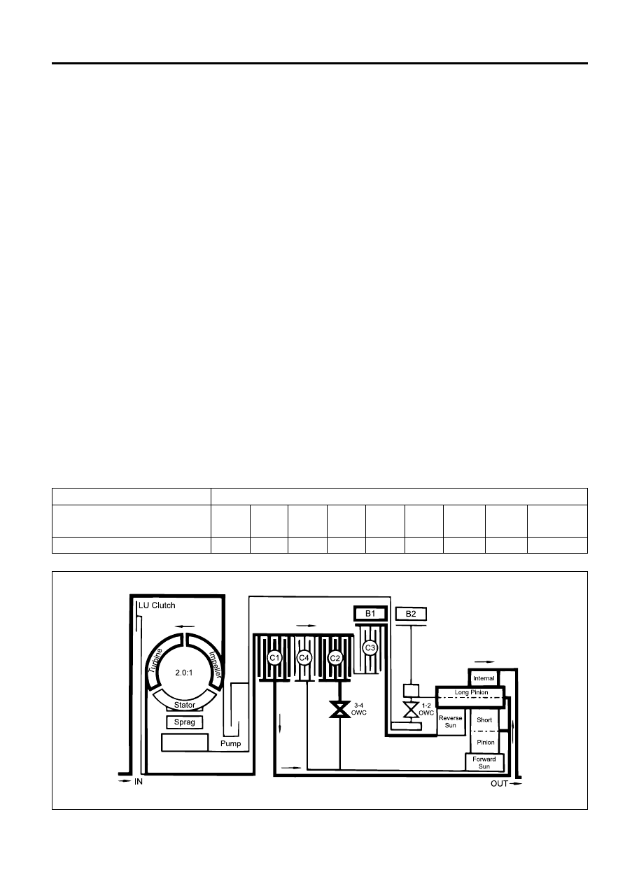
Power Flow - Drive 4 (Overdrive)

In Drive 4 (Overdrive), transmission drive is via the
input shaft to the forward clutch cylinder.

The elements of the transmission function as follows;

The C1 clutch is applied to drive the planet carrier
clockwise.

The B1 band is applied to hold the reverse sun gear
stationary.

As the planet carrier tuns, the long pinion walks
around the stationary reverse sun gear and rotates
around its axis driving the internal ring gear and
output shaft in a clockwise or forward direction at a
speed faster than the input shaft i.e. in overdrive
ratio.

The forward sun gear is also driven faster than the
input shaft and overruns the 3-4 OWC.

The C2 clutch is engaged to reduce the speed differ-
ential across the 3-4 OWC.

Control

To maintain this arrangement in the steady state sole-
noids and valves are activated as follows;

Solenoid S1 is switched ON. S2 is switched OFF.

With S1 switched ON, the 3-4 shift valve is held in
the fourth gear position by line 500 pressure on the
small end of the valve.

With S2 switched OFF, the 2-3 shift valve is held in
the fourth gear position by line 500 pressure on the
large end of the valve.

The 1-2 shift valve is held in the fourth gear position
by S2 oil pressure.

2nd oil (line pressure) from the 1-2 shift valve is di-
rected to the band apply feed regulator valve, and
to the 2-3 shift valve.

The band apply feed regulator valve supplies 2nd
oil (regulated to line pressure multiplied by the valve
ra-tio) to the Band Apply Feed (BAF) circuit.

Band apply feed oil is directed to;

- the outer apply area of the front servo

- the inner apply area of the front servo piston via

the 3-4 shift valve

- the 1-2 shift valve to provide an exhaust port

when the transmission is shifted to first gear

2nd oil at the 2-3 shift valve is directed to the 3rd
oil circuit.

3rd oil from the 2-3 shift valve is directed to the
clutch apply regulator valve, and to the 4-3
sequence valve.

The clutch apply regulator valve supplies oil (regu-
lated to line 500 pressure multiplied by the valve
ratio) to the Clutch Apply Feed (CAF) circuit.

The CAF oil is directed to;

- the C1 clutch

- the 4-3 sequence valve

Drive oil (line pressure) from the manual valve en-
gages the C2 clutch.

KAA5A460

Gear State

Drive 4 Overdrive

C1

X

C2

X

C3

-

C4

-

B1

X

B2

-

1-2

OWC

-

3-4

OWC

-

LU

CLUTCH

-

ELEMENTS ENGAGED

5A-36  AUTOMATIC TRANSMISSION

SSANGYONG  Y200

DRIVE 4 LOCK UP

KAA5A47A

AUTOMATIC TRANSMISSION  5A-37

SSANGYONG  Y200

Power Flow - Drive 4 Lock Up

In Drive 4 Lock Up, transmission drive is the same as
for  Drive 4 but with the application of the converter
lock up  clutch to provide positive no-slip converter
drive.

Control

To maintain this arrangement in the steady state sole-
noids and valves are activated as follows;

When S7 is switched ON, S7 feed oil to the converter
clutch control valve is switched OFF and allowed
to exhaust through the S7 solenoid. This allows the
valve to move to the clutch engage position.

Regulated apply feed oil, drived from drive oil at
the converter clutch regulator valve, is directed by
the converter clutch control valve to the engage side
of the converter clutch.

Converter clutch release oil is exhausted at the con-
verter clutch control valve.

Converter feed oil is re-routed by the converter clutch
control valve directly to the oil cooler and lubrication
circuit.

KAA5A480

C1

X

C2

X

C3

-

C4

-

B1

X

B2

-

1-2

OWC

-

3-4

OWC

-

LU

CLUTCH

-

ELEMENTS ENGAGED

Gear State

Drive 4 Lock Up

5A-38  AUTOMATIC TRANSMISSION

SSANGYONG  Y200

DIAGNOSIS

BASIC KNOWLEDGE REQUIRED

You must be familliar with some basic electronics to
use this section of the Service Manual. They will help
you to follow diagnostic procedures.

Notice: Lack of the basic knowledge of this transmis-
sion when performing diagnostic procedures could re-
sult in incorrect diagnostic performance or damage to

transmission components. Do not, under any circum-
stances, attempt to diagnose a transmission problem
without this basic knowledge.

Notice:  If a wire is probed with a sharp instrument
and not properly sealed afterward, the wire will corrode
and an open circuit will result.

Diagnostic test probes are now available that allow
you to probe individual wires without leaving the wire
open to  the environment. These probe devices are
inexpensive and easy to install, and they permanently
seal the wire from corrosion.

Special Tools

You should be able to use a Digital Volt Meter (DVM),
a  circuit tester, jumper wires or leads and a line
pressure gauge set. The functional check procedure
is designed to verify the correct operation of electronic
components in the transmission. This will eliminate the
unnecessary removal of transmission components.

FUNCTIONAL CHECK
PROCEDURE

Begin with the Functional Check Procedure which pro-
vides a general outline of how to diagnose automatic
transmission. The following functional check procedure
will indicate the proper path of diagnosing the transmis-
sion by describing the basic checks and then referenc-
ing the locations of the specific checks.

Check the fluid level according to the Fluid Level
Service Procedure.

Check the transmission fluid leak.

Check if the transmission fluid is not burnt by smell.
Notice: The specific fluid used in this transmission
turns brown during normal operation. Brown fluid
does not indicate a transmission fault.

Ensure that the transmission is not in Limp Home
Mode (LHM).

Check the battery terminals and the earth connec-
tions for corrosion or looseness.

Check that the cooler flow is not restricted.

Check all electrical plug connections for tightness.

Use on-board diagnostic tool or a scan tool to see
if any transmission trouble codes have been set.

DIAGNOSTIC INFORMATION AND PROCEDURES

Refer to  the appropriate “Diagnostic Trouble Code
(DTC)”  information and repair the vehicle as
directed. After  repairing the vehicle, perform the
road test and verify that the code has not set again.

Perform the Electrical/Garage Shift Tests.

Perform the Road Test Procedure in this section.

Inspect the oil and check for metal or other contami-
nants in the oil pan.

TRANSMISSION FLUID LEVEL
SERVICE PROCEDURE

This procedure is to be used when checking a concern
with the fluid level in a vehicle. A low fluid level will
result in slipping and loss of drive/ reverse or delay
on engagement of drive/ reverse when the vehicle is
cold.

The vehicle is first checked for transmission diagnostic
messages on the scan tool. If the oil level is low, it is
possible to register a vehicle speed signal fault.

The vehicle is to be test driven to determine if there is
an abnormal delay when selecting drive or reverse, or
loss of drive. One symptom of low fluid level is a
momentary loss of drive when driving the vehicle around
a corner. Also when the transmission fluid level is low,
a loss of drive may occur when the transmission fluid
temperature is  low.

If there is no loss of drive when the vehicle is driven
warm and a vehicle speed signal fault is registered,
then fluid should be added to the transmission.

When adding or changing transmission fluid use only
Castrol TQ 95 automatic transmission fluid. The use of
incorrect fluid will cause the performance and durability
of the transmission to be severely degraded.

Fluid Level Diagnosis procedure

1. If the vehicle is at operating temperature allow the

vehicle to cool down for two hours, but no greater
than four hours. Or if the vehicle is at cool status,
start the  engine and allow the engine to idle for
approximately  5 minutes or, if possible, drive the
vehicle for a few  kilometers. This will allow the
transmission to be within  the correct temperature
range. Transmission fluid level should be checked
at temperature 50 - 60 ° C (82 - 140 ° F).

Caution: Removal of the fluid filler plug when the
transmission fluid is hot may cause injury if fluid
drains from the filler hole.

2. With the brake pedal pressed, move the gear shift

control lever through the gear ranges, pausing a
few  seconds in each range. Return the gear shift
control lever to P (Park). Turn the engine OFF.


Content   ..  539  540  541  542   ..