SsangYong Rexton. Service manual - part 533


  Index      SsangYong     SsangYong Rexton - service and repair manual


Search            


Content   ..  531  532  533  534   ..


SsangYong Rexton. Service manual - part 533


AUTOMATIC TRANSMISSION  5A-3

SSANGYONG  Y200

allows the engine to be started. There is no power
transferred through the transmission in Neutral. But
the final drive is not locked by the parking pawl, so
thewheels are free to rotate.

D - Overdrive range is used for all normal driving
conditions. 4th gear (overdrive gear) reduces the
fuel  consumption and the engine noise. Engine
braking is applied with reduced throttle.

First to second (1 

 2), first to third (1 

 3), second

to third (2 

 3), second to fourth (2 

 4), third to

fourth (3 

 4), fourth to third (4 

 3), fourth to

second (4 

 2),  third to second (3 

 2), third to

first (3 

 1) and second to first (2 

 1) shifts are

all available as a function of vehicle speed, throttle
position and the time change  rate of the throttle
position.

Downshifts are available for safe passing by
depress-ing the accelerator. Lockup clutch may be
enabled in 3rd and 4th gears depending on vehicle
type.

3 - Manual 3 provides three gear ratios (first through
third) and prevents the transmission from operating
in 4th gear. 3rd gear is used when driving on long
hill  roads or in heavy city traffic. Downshifts are
available by depressing the accelerator.

2 - Manual 2 provides two gear ratios (first and
second). It is used to provide more power when
climbing hills or engine braking when driving down
a steep hill or starting off on slippery roads.

1 - Manual 1 is used to provide the maximum engine
braking when driving down the severe gradients.

When NORMAL mode is selected upshifts will occur
to maximize fuel economy. When POWER mode is se-
lected,  u p s h i f t s   w i l l   o c c u r   t o   g i v e   m a x i m u m
performance and the POWER mode indicator light is
switched ON.

When WINTER mode is selected, starting in second
gear is facilitated, the WINTER mode indicator light is
switched ON and the POWER mode indicator light is
switched OFF.

Indicator Light

The indicator light is located on the instrument panel.

Auto shift indicator light comes ON when the ignition
switch ON and shows the gear shift control lever
posi-tion.

POWER mode indicator light comes ON when the
POWER mode is selected and when the kickdown
switch is depressed.

WINTER mode indicator light comes ON when the
WINTER mode is selected.

CONTROL SYSTEMS

BTRA M74 4WD automatic transmission consists of
two  control systems. One is the electronic control
system that monitors vehicle parameters and adjusts
the transmission performance. Another is the hydraulic
control system that implements the commands of the
electronic control system commands.

ELECTRONIC CONTROL SYSTEM

The electronic control system comprises of sensors, a
TCM and seven solenoids. The TCM reads the inputs
and activates the outputs according to values stored
in Read Only Memory (ROM).

The TCM controls the hydraulic control system. This
control is via the hydraulic valve body, which contains
seven electromagnetic solenoids. Six of the seven
solenoids are used to control the line pressure, operate
the shift valves and the torque converter lock-up clutch,
and to turn ON and OFF the two regulator valves that
control the shift feel.

The seventh solenoid is the proportional or Variable
Pressure Solenoid (VPS) which works with the two regu-
lator valves to control shift feel.

Transmission Control Module (TCM)

The TCM is an in-vehicle micro-processor based trans-
mission management system. It is mounted under the
driver’s side front seat in the vehicle cabin.

The TCM contains:

Processing logic circuits which include a central mi-
croprocessor  controller and a back-up memory
system.

Input circuits.

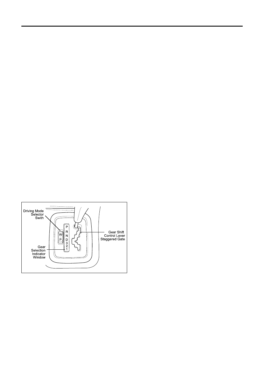
Driving Mode Selector

The driving mode selector consists of a driving mode
selector  switch and indicator light. The driving mode
selector  is located on the center console and allows
the driver to select the driving mode.

The driving modes available to be selected vary with
vehicle  types. Typically the driver should have the
option to  select among NORMAL, POWER and
WINTER modes.

KAA5A020

5A-4  AUTOMATIC TRANSMISSION

SSANGYONG  Y200

Output circuits which control external devices such
as the Variable Pressure Solenoid (VPS) driver, On/
Off solenoid drivers, a diagnostics output and the
driving mode indicator light.

Processing Logic

Shift schedule and calibration information is stored in
an Erasable Programmable Read Only Memory (EPROM).

Throttle input calibration constants and the diagnostics
information are stored in Electrically Erasable Program-
mable Read Only Memory (EEPROM) that retains the
memory even when power to the TCM is disconnected.
TCM continuously monitors the input values and uses
these, via the shift schedule, to determine the required
gear state. At the same time it monitors, via the
solenoid outputs, the current gear state, whenever the
input conditions change such that the required gear
state is different  to the current gear state, the TCM
initiates a gear shift to bring the two states back into
line.

Once the TCM has determined the type of gearshift
required the TCM accesses the shift logic, estimates

the engine torque output, adjusts the variable pressure
solenoid ramp pressure then executes the shift.

The TCM continuously monitors every input and output
circuit for short or open circuits and operating range.

When a failure or abnormal operation is detected the
TCM records the condition code in the diagnostics
memory and implements a Limp Home Mode (LHM).

The actual limp home mode used depends upon the
fail-ure detected with the object to maintain maximum
drive-ability  without damaging the transmission. In
general  input failures are handled by providing a
default value.  Output failures, which are capable of
damaging the  transmission, result in full limp mode
giving only third or fourth gear and reverse. For further
details of limp modes and memory retention refer to
the Diagnostic Trouble Code Diagnosis Section.

T h e   T C M   i s   d e s i g n e d   t o   o p e r a t e   a t   a m b i e n t
temperatures between - 40 and 85 °C (- 40 and 185 °F).
It is also protected against electrical noise and voltage
spikes, however all the usual precautions should be
observed,  for example when arc welding or jump
starting.

TCM Inputs

To function correctly, the TCM requires engine speed,
vehicle speed, transmission fluid temperature, throttle
position, gear position and Kickdown Switch inputs to
determine the variable pressure solenoid current ramp

KAA5A030

and on/off solenoid states. This ensures the correct
gear selection and shift feel for all driving conditions.

The inputs required by the TCM are as follows;

AUTOMATIC TRANSMISSION  5A-5

SSANGYONG  Y200

Engine Speed

The engine speed signal is derived from the Control-
ler Area Network (CAN) via Engine Control Module
(ECM).

Vehicle Speed

The vehicle speed sensor, which is located in the
transfer case, sends the output shaft speed signal
to the Engine Control Module (ECM). The information
is then transferred to the TCM via the CAN.

Transmission Fluid Temperature

The transmission fluid temperature sensor is a
thermistor located in the solenoid wiring loom within
the valve body of the transmission. This sensor is
a typical Negative Temperature Coefficient (NTC)
resistor  with low temperatures producing a high
resistance and high temperatures producing a low
resistance.

If the transmission fluid temperature exceeds 135
° C (275 ° F), the TCM will impose converter lock-up
at  lower vehicle speeds and in some vehicles
flashes  the mode indicator light. This results in
maximum oil flow through the external oil cooler and
eliminates  slippage in the torque converter. Both
these actions combine to reduce the oil temperature
in the transmission.

Minimum

Temperature

(°C)

Resistance (Ohms)

-20

0

20

100

135 (Overheat

Mode Threshold)

13,638

 5,177

2,278

117

75

Maximum

17,287

6,616

2, 723

196

85

Throttle Position Sensor

Gasoline Engine:

The throttle position signal is sent from the ECM to the

TCM via the CAN. Refer to Engine Section for further

details.

Diesel Engine:

The throttle position sensor(TPS) is a resistance
potentiometer which is installed on the injection pump.

It transmits a signal to the TCU proportional to the
throttle plate opening.

The potentiometer is connected to the TCU by three
wires: 5 volts positive supply, earth and variable wiper
voltage.

Throttle voltage adjustments are as follows:

Closed throttle voltage is 0.2 V to 1.0 V.

Wide open throttle voltage is 3 V to 4.5 V.

These measurements are taken between pins 1 and 3
of the TPS connentor.

Pin No.

Wire  Color

Connects to

1

Red

Solenoid 1

2

Blue

Solenoid 2

3

Yellow

Solenoid 3

4

Orange

Solenoid 4

5

Green

Solenoid 5

6

Violet

Solenoid 6

7

Brown

Solenoid 7

8

Green

Solenoid 5

9

White

Temperature Sensor

10

Red

Temperature Sensor

Pin No. Codes and colors in Solenoid Loom

KAA5A040

KAA5A050

5A-6  AUTOMATIC TRANSMISSION

SSANGYONG  Y200

Maintaining good shift feel through the transmission
life span is dependant on having an accurate measure
of the engine throttle position. To achieve this the TCU
continuously monitors the maximum and minimum
throttle potentiometer voltages and, if a change occurs,
stores the new voltage values.

However these limits will be lost and will require
relearning should a new TCU be installed, or the throttle
calibration data is cleared by the execution of a
particular sequence. This last instance depends on
the installation, and reference should be made to the
Diagnostics Section of this manual. The relearning will
happen automatically.

Shift Lever Position

      Resistance (k

)

Manual 1

 1 ~ 1.4

Manual 2

21.8 ~ 2.2

Manual 3

3 3 ~ 3.4

Drive

4.5 ~ 4.9

Neutral

6.8 ~ 7.2

Reverse

10.8 ~ 11.2

Park

18.6 ~ 19

YAD5A250

Inhibit starting of the vehicle when the shift lever is
in a position other than Park or Neutral

Illuminate the reverse lamps when Reverse is se-
lected

Indicate to the TCM which lever position has been
selected by way of a varying resistance.

Gear Position Sensor

The gear position sensor is incorporated in the inhibitor
switch mounted on the side of the transmission case.

KAA5A060

Kickdown Switch

The Kickdown Switch is used to signal the TCM that
the driver has pressed the acclerator to the floor and
requires a kickdown shift. When this switch is used,
the  POWER light comes ON and the POWER shift
pattern is used.

Diagnostic Inputs

The diagnostic control input or K-line is used to initiate
the outputting of diagnostic data from the TCM to a
diagnostic test instrument. This input may also be used
to clear the stored fault history data from the TCM’s
retentive memory. Connection to the diagnostic input
of the TCM is via a connector included in the vehicle’s
wiring harness or computer interface.

Battery Voltage Monitoring Input

The battery voltage monitoring input is connected to
the  positive side of the battery. This signal is taken
from the main supply to the TCM.

If the battery voltage at the TCM falls below 11.3 V,
the  transmission will adopt a low voltage mode of
operating in which shifts into first gear are inhibited.
All other shifts are allowed but may not occur because
of the reduced voltage. This condition normally occurs
only when the battery is in poor condition.

If the battery voltage is greater than 16.5 V, the trans-
mission will adopt limp home mode and all solenoids
are turned OFF.

When system voltage recovers, the TCM will resume
normal operation after a 30 seconds delay period.

TCM Outputs

The outputs from the TCM are supplied to the compo-
nents described below;

Solenoids

Mode Indicator Light

The gear position sensor is a multi-function switch pro-
viding three functions;

Readings for Resistance / Shift Lever Positions


Content   ..  531  532  533  534   ..