SsangYong Rexton. Service manual - part 89
DI08-9
CHANGED BY
EFFECTIVE DATE
AFFECTED VIN
ENGINE CONTROL SYSTEM
DI ENG SM - 2004.4
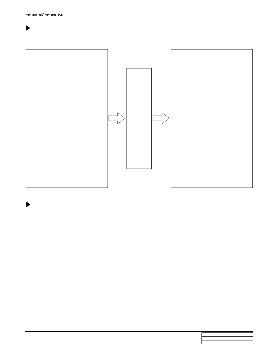
ECU Inputs·Outputs
Control
E
C
U
Structure and Function of ECU
Function of ECU
ECU receives and analyzes signals from various sensors and then modifies those signals into permissible voltage levels
and analyzes to control respective actuators.
ECU microprocessor calculates injection period and injection timing proper for engine piston speed and crankshaft
angle based on input data and stored specific map to control the engine power and emission gas.
Output signal of the ECU microprocessor drives pressure control valve to control the rail pressure and activates
injector solenoid valve to control the fuel injection period and injection timing; so controls various actuators in
response to engine changes. Auxiliary function of ECU has adopted to reduce emission gas, improve fuel economy
and enhance safety, comforts and conveniences. For example, there are EGR, booster pressure control, autocruise
(export only) and immobilizer and adopted CAN communication to exchange data among electrical systems
(automatic T/M and brake system) in the vehicle fluently. And Scanner can be used to diagnose vehicle status and
defectives.
Operating temperature range of ECU is normally -40 ~ +85°C and protected from factors like oil, water and electromag-
netism and there should be no mechanical shocks.
To control the fuel volume precisely under repeated injections, high current should be applied instantly so there is
injector drive circuit in the ECU to generate necessary current during injector drive stages.
Current control circuit divides current applying time (injection time) into full-in-current-phase and hold-current-phase and
then the injectors should work very correctly under every working condition.
Output
Injector
EGR system
Fuel pressure regulating valve (IMV)
Electrical fan control (Low/High-speed)
A/C compressor relay
Glow plug relay
Immobilizer
Warning lights
(Water warning light, glow plug indica-
tor light, engine warning light)
Preheater (auxiliary heater)
K - line
CAN communication
Self-diagnosis
Inputs
Booster pressure sensor
Atmospheric pressure sensor
(Built-in ECU)
Air flow sensor (HFM)
Coolant temperature sensor
Fuel temperature sensor
Fuel pressure sensor
Fuel filter water sensor
Knock sensor
crankshaft position sensor
camshaft position sensor
Accelerator sensor
Vehicle speed sensor
Switch input signal
(IG, brake, clutch, A/C signal, A/C
compressor)