SsangYong Rexton. Service manual - part 34
DI02-27
CHANGED BY
EFFECTIVE DATE
AFFECTED VIN
ENGINE HOUSING
DI ENG SM - 2004.4
Y220_02086
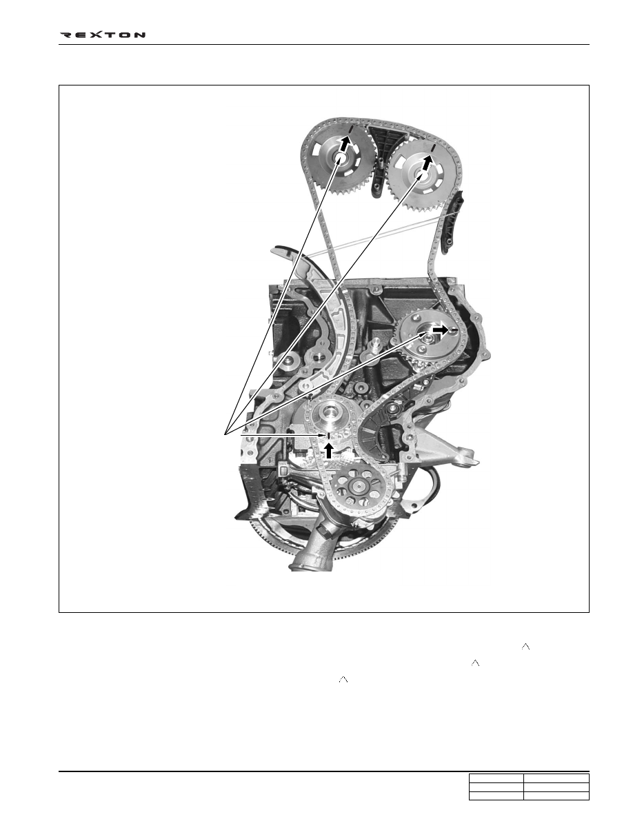
Timing setting
• Check marking links on the chain (Gold marking)
• Locate a point with two continuous marking links and align it to a marking on crankshaft sprocket (
)
• Align respective marking link to each camshaft sprocket (intake and exhaust) marking (
)
• Align another marking link to HP pump sprocket marking (
)
<Timing marking points on chain>
Sprocket marking: 4 points
(Gold marking)