SsangYong Korando II (1996-2006 year). Service manual - part 8


  Index      SsangYong     SsangYong Korando II - service and repair manual 1996-2006 year


Search            


Content   ..  6  7  8  9   ..


SsangYong Korando II (1996-2006 year). Service manual - part 8


1A1 -- 10 GENERAL ENGINE INFORMATION

DAEWOO MY_2000

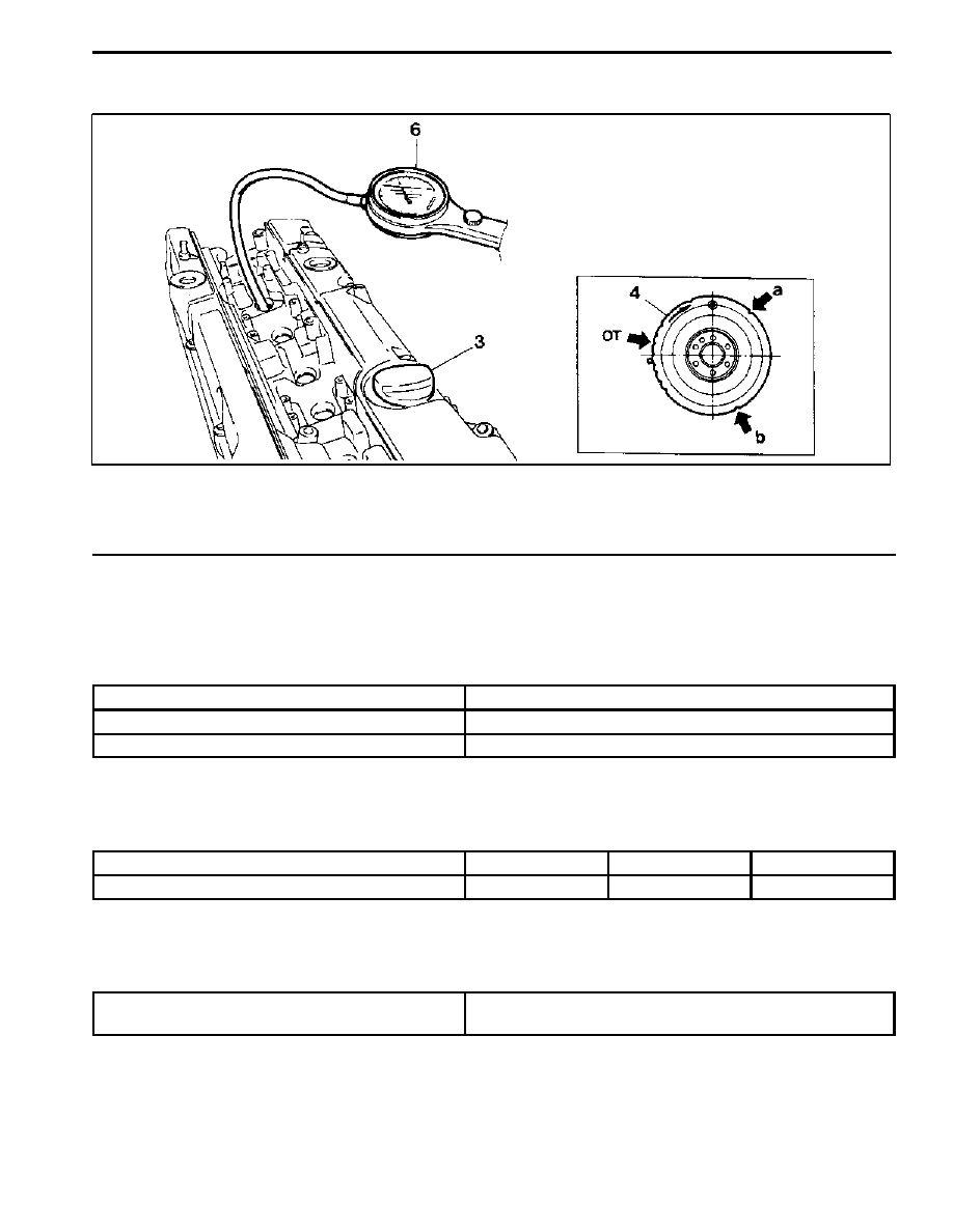
CYLINDER PRESSURE LEAKAGE TEST

3 Engine Oil Filler Cap

4 Vibration Damper

6 Cylinder Pressure Leakage Tester with

Connecting Hose

Permissible Pressure Leakage

At Whole Engine

Max. 25 %

At Valve and Cylinder Head Gasket

Max. 10 %

At Piston and Piston Ring

Max. 20 %

Cylinder Number By Mark On Vibration Damper At TDC

TDC Mark

OT (TDC)

a (120°)

b (240°)

Cylinder Number

1, 6

2, 5

3, 4

Universal Tool

Cylinder Pressure Leakage Tester

Bosch, EFAW 210A

Sun, CLT 228

GENERAL ENGINE INFORMATION 1A1 -- 11

DAEWOO MY_2000

Leakage Test

1. Warm the engine up to normal operating tempera-

ture.

2. Disconnect the negative battery cable.
3. Remove the spark plugs.
4. Check the coolant level by opening the coolant

surge tank cap and replenish if insufficient.

5. Open the engine oil filler cap.
6. Connect the tester to air pressure line and adjust the

scale of tester.

7. Install the connecting hose to spark plug hole.

8. Position the piston of No.1 cylinder at TDC by rotat-

ing the crankshaft.

9. Connect the connecting hose to tester and measure

the leakage volume after blowing up compressed

air.

Notice: Measure the leakage volume in the completely

opening condition of throttle valve by pulling the accel-

eration cable.
10. Perform the pressure test according to the firing or-

der.

Notice:
Firing Order : 1 -- 5 -- 3 -- 6 -- 2 -- 4
11. Compare the leakage pressure with the specifica-

tions.

1A1 -- 12 GENERAL ENGINE INFORMATION

DAEWOO MY_2000

GENERAL INFORMATION

CLEANLINESS AND CARE

An automobile engine is a combination of many ma-

chined, honed, polished and lapped surfaces with toler-

ances that are measured in the ten-thousandths of an

inch. When any internal engine parts are serviced, care

and cleanliness are important. A liberal coating of enigne

oil should be applied to friction areas during assembly, to

protect and lubricate the surfaces on initial operation.

Proper cleaning and protection of machined surfaces and

friction areas is part of the repair procedure. This is con-

sidered standard shop practice even if not specifically

stated.

Whenever valve train components are removed for ser-

vice, they should be kept in order. They should be

installed in the same locations, and with the same mating

surfaces, as when they were removed.
Battery cables should be disconnected before any major

work is performed on the engine. Failure to disconnect

cables may result in damage to wire harness or other

electrical parts.

ON-ENGINE SERVICE

Caution: Disconnect the negative battery cable be-

fore removing or installing any electrical unit, or

when a tool or equipment could easily come in con-

tact with exposed electrical terminals. Disconnect-

ing this cable will help prevent personal injury and

damage to the vehicle. The ignition must also be in

LOCK unless otherwise noted.
Notice: Any time the air cleaner is removed, the intake

opening should be covered. This will protect against ac-

cidental entrance of foreign material, which could follow

the intake passage into the cylinder and cause exten-

sive damage when the engine is started.

DAEWOO MY_2000

SECTION 1B1

M162 ENGINE MECHANICAL

CAUTION: Disconnect the negative battery cable before removing or installing any electrical unit or when a

tool or equipment could easily come in contact with exposed electrical terminals. Disconnecting this cable

will help prevent personal injury and damage to the vehicle. The ignition must also be in LOCK unless other-

wise noted.

TABLE OF CONTENTS

Specifications

1B1--2

. . . . . . . . . . . . . . . . . . . . . . . . . . . .

Fastener Tightening Specifications

1B1--2

. . . . . . . . . .

Special Tools

1B1--4

. . . . . . . . . . . . . . . . . . . . . . . . . . . . .

Special Tools Table

1B1--4

. . . . . . . . . . . . . . . . . . . . . . .

Maintenance and Repair

1B1--7

. . . . . . . . . . . . . . . . . . .

On--Vehicle Service

1B1--7

. . . . . . . . . . . . . . . . . . . . . . . . .

Engine Assembly

1B1--7

. . . . . . . . . . . . . . . . . . . . . . . . .

Crankcase Ventilation System

1B1--14

. . . . . . . . . . . . .

Generator

1B1--16

. . . . . . . . . . . . . . . . . . . . . . . . . . . . . .

Engine Mount

1B1--17

. . . . . . . . . . . . . . . . . . . . . . . . . . .

Poly V--Belt

1B1--18

. . . . . . . . . . . . . . . . . . . . . . . . . . . . .

Tensioning Device

1B1--20

. . . . . . . . . . . . . . . . . . . . . . .

Poly V--Belt Inspection

1B1--21

. . . . . . . . . . . . . . . . . . .

Cylinder Head Cover

1B1--24

. . . . . . . . . . . . . . . . . . . . .

Cylinder Head Front Cover

1B1--26

. . . . . . . . . . . . . . .

Cylinder Head

1B1--28

. . . . . . . . . . . . . . . . . . . . . . . . . . .

Timing Gear Case Cover

1B1--31

. . . . . . . . . . . . . . . . .

Crankshaft Sealing Rear Cover

1B1--33

. . . . . . . . . . .

Belt Pulley and Vibration Damper

1B1--35

. . . . . . . . . .

Crankshaft Front Radial Seal

1B1--38

. . . . . . . . . . . . .

Crankshaft Rear Radial Seal

1B1--40

. . . . . . . . . . . . . .

Crankshaft

1B1--41

. . . . . . . . . . . . . . . . . . . . . . . . . . . . .

Flywheel / Driven Plate

1B1--47

. . . . . . . . . . . . . . . . . . .

Camshaft Adjuster

1B1--50

. . . . . . . . . . . . . . . . . . . . . . .

Camshaft Sprocket Bolt

1B1--52

. . . . . . . . . . . . . . . . . .

Camshaft

1B1--54

. . . . . . . . . . . . . . . . . . . . . . . . . . . . . .

Camshaft Timing Position

1B1--59

. . . . . . . . . . . . . . . .

Valve Spring

1B1--62

. . . . . . . . . . . . . . . . . . . . . . . . . . . .

Valve Stem Seal

1B1--66

. . . . . . . . . . . . . . . . . . . . . . . .

Chain Tensioner

1B1--67

. . . . . . . . . . . . . . . . . . . . . . . . .

Timing Chain

1B1--70

. . . . . . . . . . . . . . . . . . . . . . . . . . . .

Tensioning Rail

1B1--75

. . . . . . . . . . . . . . . . . . . . . . . . . .

Cylinder Head Guide Rail

1B1--76

. . . . . . . . . . . . . . . . .

Crankcase Guide Rail

1B1--77

. . . . . . . . . . . . . . . . . . . .

Crankshaft Sprocket

1B1--78

. . . . . . . . . . . . . . . . . . . . .

Piston

1B1--80

. . . . . . . . . . . . . . . . . . . . . . . . . . . . . . . . . .

Connecting Rod

1B1--83

. . . . . . . . . . . . . . . . . . . . . . . . .

Piston Ring

1B1--85

. . . . . . . . . . . . . . . . . . . . . . . . . . . . .

Engine Oil Specification

1B1--87

. . . . . . . . . . . . . . . . . .

Oil Pan

1B1--88

. . . . . . . . . . . . . . . . . . . . . . . . . . . . . . . . .

Engine Oil and Oil Filter Element

1B1--90

. . . . . . . . . .

Oil Filter

1B1--92

. . . . . . . . . . . . . . . . . . . . . . . . . . . . . . . .

Oil Pump

1B1--94

. . . . . . . . . . . . . . . . . . . . . . . . . . . . . . .

Oil Pressure Relief Valve

1B1--96

. . . . . . . . . . . . . . . . .

Oil Non-Return Valve

1B1--97

. . . . . . . . . . . . . . . . . . . .

Oil Dipstick Guide Tube

1B1--98

. . . . . . . . . . . . . . . . . .

Unit Repair

1B1--99

. . . . . . . . . . . . . . . . . . . . . . . . . . . . . .

Oil Gallery in Crankcase

1B1--99

. . . . . . . . . . . . . . . . . .

Oil Gallery in Cylinder Head

1B1--101

. . . . . . . . . . . . . .

Core Plugs in Crankcase

1B1--104

. . . . . . . . . . . . . . . .

Cylinder Bore

1B1--106

. . . . . . . . . . . . . . . . . . . . . . . . . .

Crankcase Mating Surface

1B1--108

. . . . . . . . . . . . . .

Cylinder Head Mating Surface

1B1--110

. . . . . . . . . . .


Content   ..  6  7  8  9   ..