Renault Grand Scenic (2016 year). Manual - part 14
5.16
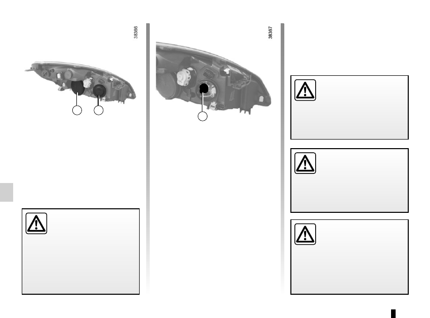
FRONT HEADLIGHTS: changing bulbs
(1/3)
A special mounting is re-
quired to fit this type of
headlight, it is forbidden to
fit a headlight with xenon
bulbs to a vehicle which was not
designed for it.
Due to the danger involved
in handling high-voltage de-
vices, this type of bulb must
be replaced by an approved
dealer.
Discharge bulb main beam
headlights/dipped beam
headlights
Never open cover A
Bulb type: D1S.
Direction indicator lights
Remove the cover B, pull on the bulb
holder wire 1, remove the bulb and re-
place it.
Bulb type: PY21W.
The engine may be hot
when carrying out opera-
tions in close proximity. In
addition, the engine cooling
fan can come on at any moment.
Risk of injury.
The bulbs detailed below can be re-
placed. However, we recommend that
these be replaced by an approved
Dealer if this proves difficult.
A
B
1
Before performing any
action in the engine com-
partment, the ignition must
be switched off by pressing
the engine stop button (please see
the information on “Starting, stop-
ping the engine” in Section 2).