Dacia Pick-Up 1304/1305/1307. Service manual - part 143


  Index      Dacia     Dacia Pick-Up 1304/1305/1307 (Engine F8Q) - service and repair manual 2004 year


Search            


Content   ..  141  142  143  144   ..


Dacia Pick-Up 1304/1305/1307. Service manual - part 143


89

ELECTRICAL DIAGRAMS

89 - 11

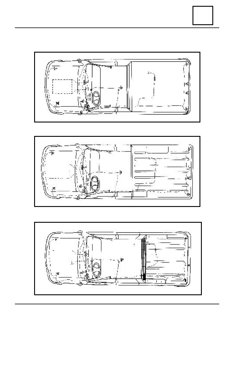
FIXATION OF ELECTRIC MASS ON THE VEHICLE

A. for U75 (Pick-up), M75 (King Cab)

B. for E75 (Drop -Side)

C. for H75 (Double Cab)

MU

MF

MG

MB

MA

MN

MA

MB

MN

MU

MF

MG

MA

MB

MN

MU

MG

MF

89

ELECTRICAL DIAGRAMS

89 - 12

Electronic clock
Left front door contact
Cockpit fuses box
Decoder UCE

Control relay for climate GMV  - step1

Right front ceiling light
Fuel level transmitter and electric pump
Right rear light
Right registration number light
Left registration number light
Left rear lamp
Left front side signalisation light
Left front brake plates

Safety  fuses and relays  box , engine compart.

A.C compressor clutch
Left front signalisation light
Left headlight
Left fog headlight
Alternator
Cooling GMV and A.C
Water thermocontact - 2 steps
Right fog headlight
Air conditioning pressure gauge
Right headlight
Right front signalisation light
Acoustic alarm
Windscreen wiper timer
Idle running contactor
A.C relay (board)
Manual contact
Diagnosis socket
Fog headlights control relay

ELECTRIC COMPONENTS LOCATION ON THE VEHICLE

Breakdown switch
Fog lights switch
Safety belt witness
Fog headlights switch
Air heater switch
Anti-starter receptor

Air conditioning control (pusch button + switch )

Indicating relay for over-limit speed 120km/h

Rotation sensor
Vacuum capsule contact
Supplyinig plate (+DC)
Windscreen wiper motor
Climate control GMV
Cockpit GMV2  (for A.C)
Oxygen rod
Signalisation relay
Braking system ICP
Supplying plate  (+IC)
Windscreen wiper-cleaner switch
Anti-theft system

Switch for lights, signalisation, direction,horn

Handbrake contact
Contactor centurã conducãtor
Canister purging valve
Water temperature transmitter
Injector water temperature sensor
Valve potentiometer
Engine step by step
Injection air temperature sensor
Ignition coil
 4x4 coupling electro valve
Injection computer (UCE)
Right front brake plate
Right front side signalisation light

1
2
3
4
5
6
7
8
9
10
11
12
13
14
15
16
17
18
19
20
21
22
23
24
25
26
27
28
29
30
31
32
33
34

35
36
37
38
39
40
41
42
43
44
45
46
47
48
49
50
51
52
53
54
55
56
57
58
59
60
61
62
63
64
65
66
67
68

89

ELECTRICAL DIAGRAMS

89 - 13

B. PENTRU E75 (Drop -Side)

A. PENTRU U75 (Pick-up), M75 (King Cab)

41

42

43

44

45

40

23

22

20

19

21

4

3

2

1

5

8

16

18

61

11

17

63

38

37

36

46

47

65

48

66

49

60

50

51

52

53

54

55

56

57

58

59

29

27

28

25

26

30

64

24

15

10

62

9

13

14

31 32 33

34

35

39

7

12

41

42

43

44

45

40

23

22

7

20
19

21

4

3

2

1

5

6

8

39

16

18

61

11

17

63

38

37

36

46

47

65

48

66

49

60

50

51

52

53

54

55

56

57

58

59

29

27

28

25
26

30

64

24

15

10

62

9

13

14

31 32 33

34

35

12

ELECTRIC COMPONENTS LOCATION ON THE VEHICLE

89

ELECTRICAL DIAGRAMS

89 - 14

C. PENTRU  H75 (Double Cab)

40

23

22

20
19

21

4

3

2

12

56

8

16
18

61

11

17

63

38

37

36

46

47

65

48

66

49

60

50

51

52

53

54

55

56

57

58

59

29

27

28

25

26

30

64

24

15

10

62

9

13

14

31 32 33

34

35

39

7

41

42

43

44

45

1

ELECTRIC COMPONENTS LOCATION ON THE VEHICLE


Content   ..  141  142  143  144   ..