Dacia Pick-Up 1304/1305/1307. Service manual - part 136


  Index      Dacia     Dacia Pick-Up 1304/1305/1307 (Engine F8Q) - service and repair manual 2004 year


Search            


Content   ..  134  135  136  137   ..


Dacia Pick-Up 1304/1305/1307. Service manual - part 136


INSTRUMENT PANEL

83

83 - 16

NOTE: The temperature transmitter  may not be repaired. It is attached on the clos-

ing plate of the cylinder head.

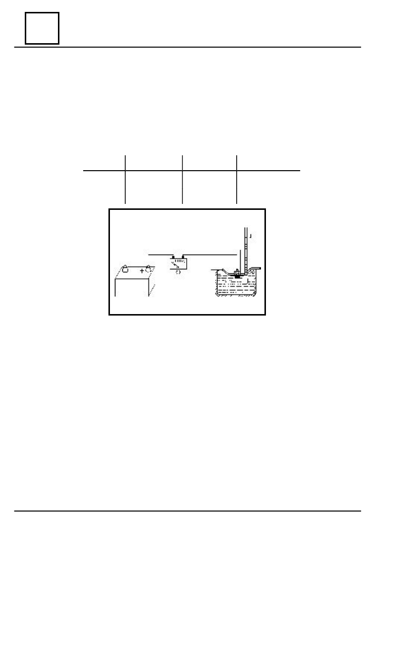
In order to perform the checking there are necessary:  a vessel with cooling fluid

(antifreeze + distilled water ), a thermometer 0 – 200° C, a heat source,  an ohm meter.

Make an assembly according to the diagram. The variation of  the resistance (R) in function of

the temperature (T) must be according to the following table:

T [ 

0

 C ]

60 

0

 +/- 5

 0

90 

0

 +/- 4 

 0

120 

0

 +/- 5

 0

R [ 

 ]

  1010

    342                   139

 TEMPERATURE TRANSMITTER CHECKING

83

INSTRUMENT PANEL

83 - 17

D

ISMO UNTING

Disconnect the battery.
Disconnect the transmitter connector from the rear wiring.
Rotate the gauge attachment flange anti-clockwise by about 1/3 rotation.
Take out the transmitter from the tank, by lift it carefully.

R

EMOUNTING

Perform in the reverse order the dismounting operations.

NOTE:

When remounting, pay attention that rubber sealing gasket of the transmitter to be

in good state and flange to tightly fix it on the tank.

FUEL LEVEL TRANSMITTER

84

CONTROLS - SIGNALLING

84 - 1

ANTI THEFT MECHANISM REPLACEMENT

STARTING

 - 

IGNITION


SWITCH

 )

 The anti theft mechanism is placed on the right part of the steering column and has the

purpose to starter control when electric wiring is connected, being provided in the same
time also with a steering locking device, with anti theft lock.

 C

O NTACT


K EY


PO SITIONS

  P

OSITION

    I

NTERPRETATION

      O

BSERVATIONS

S

A

I

M

D

Stop anti theft
   ( parking )

Accessories

Intermediary

Engine contact

Starter contact


This position enables the introduction and taking out of

the key from the contact switch. When key is taken out
from the contact switch, the steering is blocking. Unblock-
ing is obtained by introducing the key in the contact switch
and if necessary, the easy rotation in both senses of the
steering wheel.

    In this position, accessories are voltage supplied,
protected by means of a bridge fuse F 02
   This position enables the removing of the anti theft
mechanism, after its attachment screw on the steering
column has been dismounted and the mechanism
blocking pin has been pressed.
   In this position, the steering is not blocked and all
consumers are voltage supplied, protected by means
of the bridge fuse F 01 ( inside fuse box) as well as
the injection system relays.
     This position enables the voltage supply of the
starter and engine starting, after that key is returning
in M position
   The mechanism is such built not to enable the passage
in succession of the contact key in the D position
without returning in S position

   Subject to the vehicle manufacturing variant, on the anti theft mechanism there is not
any more marked  G position ( garage ) because does not enable the taking out of the key in
this position but helps in pin unblocking for removing the mechanism from the steering
column.

STARTING - IGNITION SWITCH

CONTROLS - SIGNALLING

84

D

ISMO UNTING

Disconnect the battery
Dismount the half steering wheel housings.
Disconnects the connecting plugs of the

contact switch.

Bring the key in G position.
Unscrew the attachment screw (1).
Press the mobile pin (2) and draw the

contact backwards.

R

EMOUNTING

Mount the contact in its seat.
Tighten the attachment screw (1).
Connect:

- the contact switch;
- the battery.

Check the contact switch operation.
Mount the steering wheel housings and

the contact switch cover.

CONNECTING PLUGS REPLACEMENT

The operations are to be performed after dismounting the contact  switch from the vehicle.

D

ISMO UNTING

Dismount the attachment screws of the

blocking wedge guiding.

Dismount the connecting plugs.

R

EMO UNTING

Position and mount the connecting plugs.
Mount the blocking wedge guiding.
Tighten the attachment screws of the

blocking wedge guiding.

84 - 2

STARTING - IGNITION SWITCH


Content   ..  134  135  136  137   ..