Dacia Pick-Up 1304/1305/1307. Service manual - part 104


  Index      Dacia     Dacia Pick-Up 1304/1305/1307 (Engine F8Q) - service and repair manual 2004 year


Search            


Content   ..  102  103  104  105   ..


Dacia Pick-Up 1304/1305/1307. Service manual - part 104


LOWER STRUCTURE

41

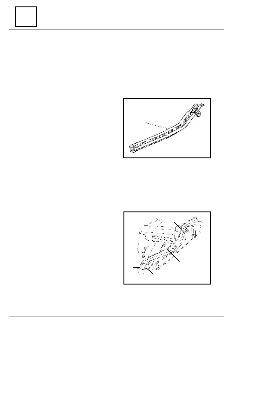
 INTERMEDIARY LONGITUDINAL GIRDER

REPLACEMENT

This operation shall be performed only on the repair bench. For the specific supports

mounting on the bench, please see the 40 chapter.

D

ISMO UNTING

Dismount the elements, which are in contact

with the intermediary longitudinal girder.

Detach the welding points of the intermediary

longitudinal girder (1) that are connecting with:

- the longitudinal girder in the area (4);
- the pedal floor in the area (2);
- the lateral cross bar in the area (3);
- the central floor in the area (5);
- rear longitudinal girder in the area (7).
Straighten the areas resulted by dismounting.
Grind the areas resulted by dismounting.

Position and center the new element.
Check the correct positioning of the

intermediary longitudinal girder.

Weld the intermediary longitudinal girder

following the assembly outliners 2,3,4,5,6.

Protect the new element with a corrosion

preventing and noise absorbent product.

R

EMO UNTING

 41 - 4

1

5

6

4

2

3

41

LOWER   STRUCTURE

 REAR LONGITUDINAL GIRDER  ( Dacia 1304 )

REPLACEMENT

This operation shall be performed only on the repair bench. For the specific supports

mounting on the bench, please see the 40 chapter.

D

ISMO UNTING

Dismount the elements, which are in

contact with the rear longitudinal girder.

Detach the welding points of the rear

longitudinal girder (1) which are in con-
tact with:

- the front cross bar in the area (2);
- the inner frame in the areas (4),(5),(6);
- the rear end cross bar in the area (3);
- the middle cross bar in the area (9);
- the spare wheel cross bar in the area (8);
- the central cross bar in the area (10);
- the rear floor in the area (3).
Straighten the areas resulted by

dismounting.

Grind the areas  resulted by dismounting.

R

EMO UNTING

Position and center the new element.
Check the correct positioning of the rear

longitudinal girder.

Weld the rear longitudinal girder (1)

after the ass embling outliners

2,3,4,5,6,7,8,9,10.

Perform two C0 2 welding layers in the

connecting area of the rear longitudinal
girder with the front cross bar, central,
middle and the spare wheel cross bar.

Protect the new  element with a corrosion

preventing and noise absorbent product.

 41 - 5

Rear longitudinal girder

Spare wheel cross bar

Front  cross

member

Rear longitudinal girder

SECO

2

2cordon X 40mm

SECO

2

2cordon X 45mm

Middle cross member

SECO

2

2cordon X 20mm
1cordon X 40mm

SECO

2

2cordon
X 45mm

Central cross member

1

2

3

4

5

6

7

9

10

8

Rear longitudinal
 girder

Rear longitudinal
 girder

LOWER STRUCTURE

41

 REAR LONGITUDINAL GIRDER ( Dacia 1307 )

REPLACEMENT

This operation shall be performed only on the repair bench. For the specific supports

mounting on the bench, please see the 40 chapter

D

ISMO UNTING

Dismount the elements  which are in contact

with the rear longitudinal girder.

Detach the welding points of the rear

longitudinal girder (1)  which are connecting
with:

- the front cross bar in the area (2);
- the lateral plate in the areas (4), (5),(6);
- the rear end cross bar in the area (7);
- the middle cross bar in the area (9);
- the spare wheel cross bar in the area (8);
- the central cross bar in the area (10);
- the rear floor in the area (3).

Straighten the areas resulted by dismounting.
Grind the areas resulted by dismounting.

R

EMO UNTING

Position and center the new element.
Check the correct positioning of the rear

longitudinal girder.

Weld the rear longitudinal girder (1)

following the assembling outliners
2,3,4,5,6,7,8,9,10.

Perform two welding layers in the connecting

areas of the rear longitudinal girder with the
front cross bar, central, middle and the spare
wheel cross bar.

Protect the new element with a corrosion

preventing and noise absorbent product.

 41 - 6

Middle cross member

Rear longitudinal
girder

Rear longitudinal
girder

SECO

2

2cordon X 20mm
1cordon X 40mm

SECO

2

2cordon
X 45mm

Central cross
member

Rear longitudinal girder

Spare wheel cross bar

   Front  cross

member

Rear lo n g itu d in al
girder

SECO

2

2cordon X 40mm

SECO

2

2cordon X 45mm

1

2

3

4

10 9

8

7

6

5

42

UPPER FRONT STRUCTURE

  42 - 1

D

ISMO UNTING

FRONT WING

Dismount the elements which are in contact with the front wing ( front bumper, the

turning lamp from the wing).

Dismount from the front wing the following screws:

- in  (1) at the upper part;
- in (2) at the connection of the wing with the front grill, at the lower part;
- in (3) at the connection of the wing with the front pillar (it is not necessary

dismounting of the front door);

- in (4) at the lower part of the body.

PREPARATION

Apply by means of a brush a layer of thermo- weldable product class. 33 B CS 4603 – 202

on the contact areas of front wing with : front wing lining, front grill and front pillar.

Apply a sealant material layer type 223 in the contact area of the front wing with: the

front wing lining, the lateral frame, and front pillar.

R

EMO UNTING

Perform the dismounting operations in the reverse order.

4


Content   ..  102  103  104  105   ..