Index Dacia Dacia Pick-Up 1304/1305/1307 (Engine F8Q) - service and repair manual 2004 year
Search
Content .. 98 99 100 101 ..
Dacia Pick-Up 1304/1305/1307. Service manual - part 100
40
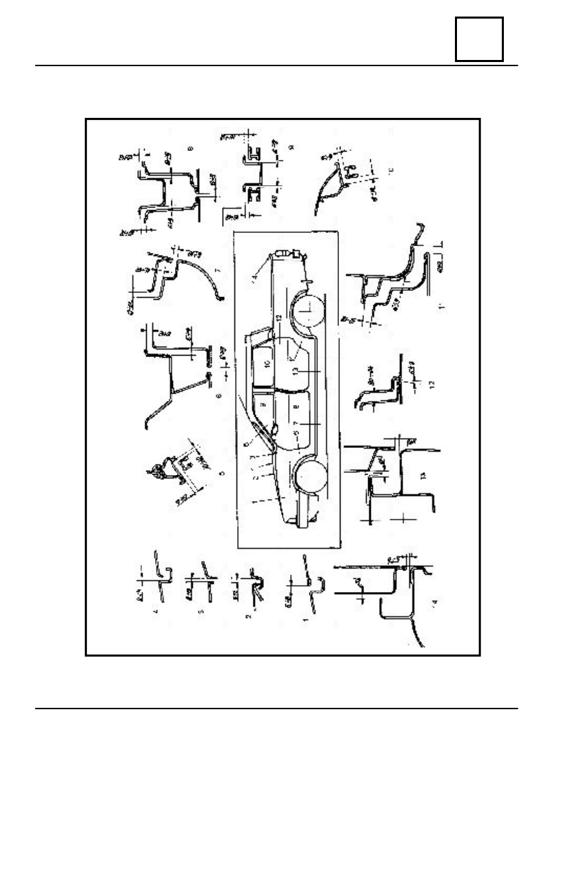
GENERAL
40 - 7
OPENINGS CLEARANCES