Dacia Pick-Up 1304/1305/1307. Service manual - part 95


  Index      Dacia     Dacia Pick-Up 1304/1305/1307 (Engine F8Q) - service and repair manual 2004 year


Search            


Content   ..  93  94  95  96   ..


Dacia Pick-Up 1304/1305/1307. Service manual - part 95


37

MECHANICAL ELEMENTS CONTROLS

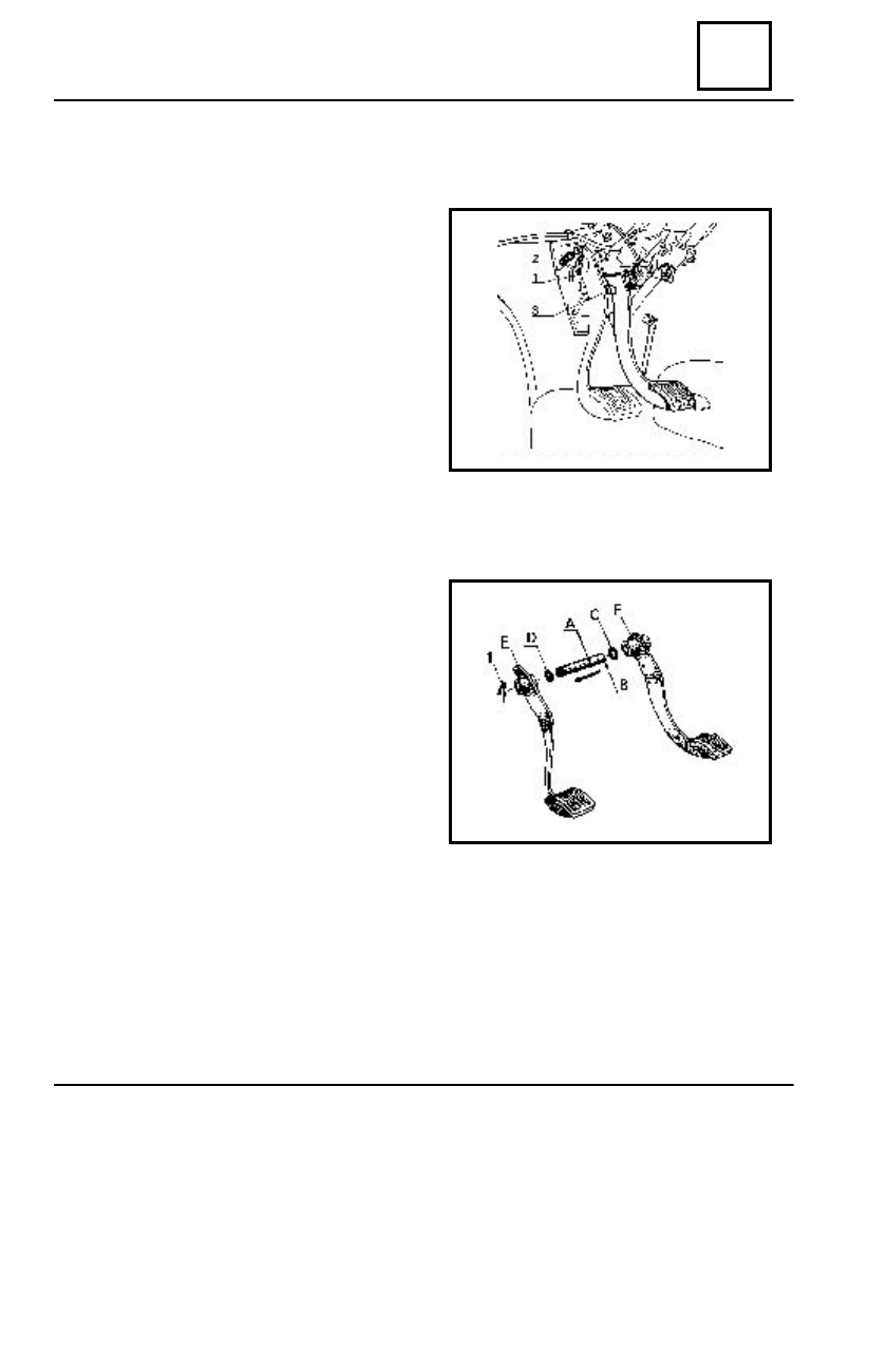
BRAKE PEDAL AND CLUTCH

D

ISMO UNTING

Remove the safety clip (1).
Detach the spring (2) of the clutch cable

shaft.

Remove the pins and the shaft (3) of

the main cylinder pushing rod.

Remove the clutch pedal from the

pedals shaft.

By means of a bronze nail, push the

pedals shaft towards the right, then
remove the brake pedal.

R

EMO UNTING

Grease the shaft (A) with special grease

containing MoS2.

Mount in the following order:

-

the brake pedal(F);

-

the washer (C).

Place the shaft (A) together with the

elastic pin (B) in the pedal support.

Place the  shaft in the second support

bore, then place the following items:

-

the washer (D);

-

the clutch pedal (E).

Check that the elastic pin (B) is well

set in its seat.

Mount the safety lock (1).
Attach the following parts:

-

the clutch cable;

-

the pushing rod of the main cylinder, on the brake pedal.

Adjust:

-

the clutch stroke;

-

the brake stroke.

37 - 15

MECHANICAL ELEMENTS CONTROLS

37

CLUTCH CABLE – CLUTCH STROKE ADJUSTMENT

CLUTCH CABLE REPLACEMENT

D

ISMO UNTING

Dismount  the clutch  lever cable.
Dismount the attachment clip (1) of the

pedal.

Push the shaft rightward and take out the

pedal.

Release the spring (2) and the shaft (3) of

the fork.

Dismount the fork.
Release the cable from the housing stopper

on the pedal support and dismount it.

R

EMO UNTING

Perform the dismounting operations in the reverse order.
Grease :

-

the pedal shaft;

-

the fork shaft.

Adjust the clutch stroke.

CLUTCH GEAR STROKE ADJUSTMENT

Loosen the lock nut (1).
Tighten or unscrew the nut (2) until

obtaining the 2,5-3,5 mm stroke at the lever
end.

Lock the lock nut.

37 - 16

37

MECHANICAL ELEMENTS CONTROLS

          THE STEERING COLUMN SUPPORT ASSY AND FIRE WALL

D

ISMO UNTING

Dismount the throttle, brake and clutch pedals.
Dismount the attachment screws (2) of the steering column mounting (1) on the wall

metal.

R

EMO UNTING

Perform the dismounting operations in the reverse order by screws tightening at the

moment of 1,5 – 2,5 daNm.

37 - 17

2

1

MECHANICAL ELEMENTS CONTROLS

37

THROTTLE PEDAL REPLACING

D

ISMO UNTING

Release the throttle pedal by dismounting the clip (8),the washer (7) and support shaft

(6).

Dismount the attachment nuts of the pedal support (2) and release the throttle pedal (3).

R

EMO UNTING

Perform the dismounting operations in the reverse order then adjust the throttle stroke

at the “ maximum” position of the valve, which is obtained by pedal pressing till its
calibration on the limiter (4) and by threaded pin adjustment (5) in this position.

                        THROTTLE CONTROL CABLE REPLACEMENT

D

ISMO UNTING

Dismount the attachment screw  of the cable(1) from the throttle control lever,then

remove the clips (8) the washer (7), and the pedal shaft (6),releasing the attachment throttle
pedal.

R

EMO UNTING

Perform the dismounting operations in the reverse order, followed by the corresponding

adjustment of the throttle pedal.

37 - 18

 THROTTLE PEDAL

1

2

3

4

6

7

8

5


Content   ..  93  94  95  96   ..