Dacia Pick-Up 1304/1305/1307. Service manual - part 91
36
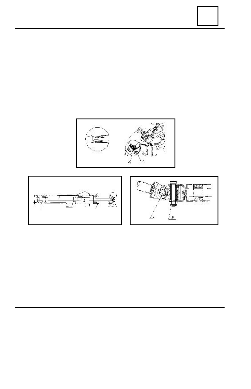
STEERING ASSEMBLY
Tighten the lower nut (A) of the cardan.
Rotate the steering wheel to the left or to the right and tighten the lower nut (B) of the
cardan.
When the steering gear is in the central point (the wheels in straight line), one of the
ends of the cardan screws should be oriented upwards.
Mount:
- the lights control switch;
- the steering wheel;
- the lower half casing;
- the ignition/starting contact.
R
EMO UNTING
Place an old lower bushing, with the diameter diminished by 2mm, under the new
lower bushing(1).
Push the steering wheel shaft (3) upwards until the lower bushing gets in its seat.
Push downwards the steering wheel shaft and recover the old bushing.
Mount the new upper bushing (2) by means of a pipe.
Check the correct positioning of the bushings in their respective seats.
Mount the safety ring (4) of the upper bushing.
Bring the steering gear to its central point.
STEERING WHEEL SHAFT BUSHING
36 - 15
1
3
2
4
4