Dacia Pick-Up 1304/1305/1307. Service manual - part 84
33
REAR BEARING ELEMENTS
33 - 27
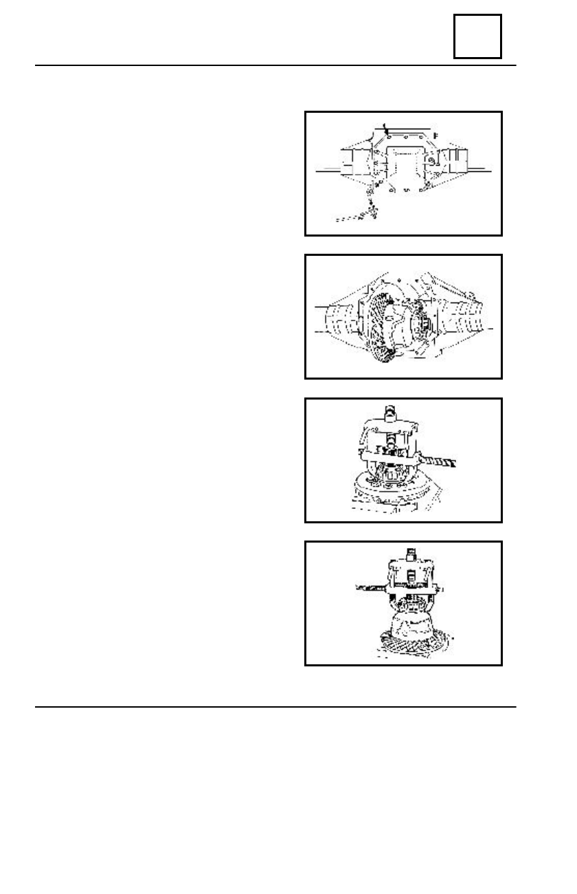
CAST IRON REAR DRIVE AXLE DIFFERENTIAL
From the back part of the axle dismount the
cap of the axle , by unscrewing the fourteen M 8
screws.
Remove the G 3 – 36 and G 5 – 36 elastic
pins of the slotted bushing , by means of the 31
B set of mandrels, marking the position of the
bushing and shifting it towards the exterior.
Dismount the adjustment nuts retainers, mark-
ing the position of the nuts in correspondence
with the casing.
Unscrew the bearings nuts.
Dismount the bearings half casings by
unscrewing the M 10 screws.
Remove the differential gear assembly from
the rear axle casing, together with the two bi-
conical balls bearings.
From the back part of the axle also remove
the differential drive pinion together with the 35
x 80 x 32,75 conical balls bearing.
Dismount the two opposite screws that
attach the rim.
Depress the bearings by means of the
CV 28 A provided with CV 48 grippers.
Dismount the rim ; the screws shall not be
reused.