Dacia Pick-Up 1304/1305/1307. Service manual - part 63


  Index      Dacia     Dacia Pick-Up 1304/1305/1307 (Engine F8Q) - service and repair manual 2004 year


Search            


Content   ..  61  62  63  64   ..


Dacia Pick-Up 1304/1305/1307. Service manual - part 63


29

DRIVE SHAFTS

BELLOWS TOWARDS  THE WEEL

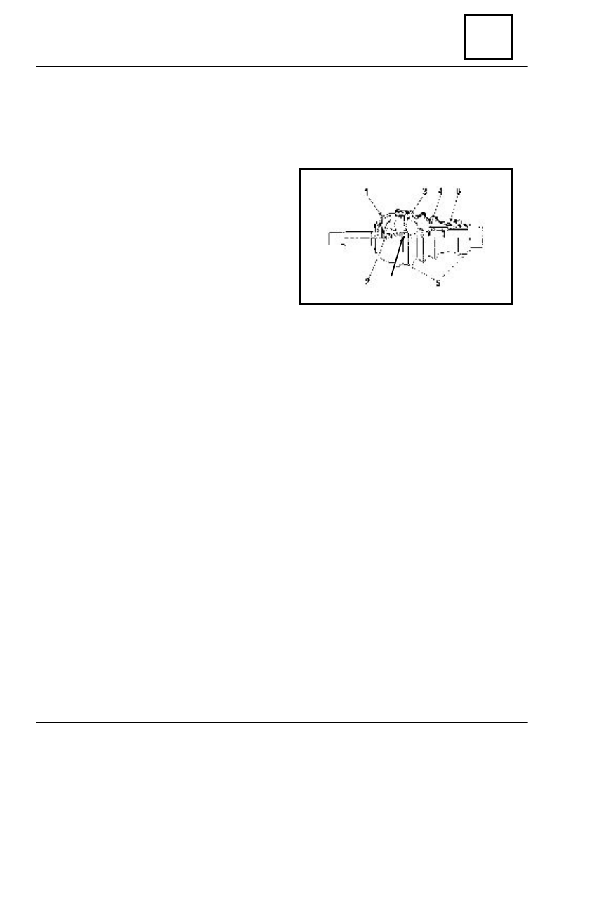
 GE 86 JOINT BELLOWS REPLACEMENT

Bellows replacement – the wheel side- is to be performed having the transmission

dismounted.

1

. Steering knuckle casing

2

. Retention star

3

. Tripod assembly

4

. Tulip shaft

5

. Collars

6

. Bellows

7

. Spring

D

ISMO UNTING

Remove the two collars (5) taking care not to damage the channels made on the steering

knuckle surface.

Cut and remove the damaged bellows.
Take out maximum of grease.
For GE joint bellows replacement it will be necessary to dismount the joint parts

towards the gearbox (joint JI 69) ( see previously described method).

R

EMO UNTING

NOTE:
It is absolutely necessary to observe the prescribed grease quantity  ( 26,0 cl ).

Position: the bellows reinforcements in the steering knuckle casing channels and in the shaft

rod channel.

Mount the GE joint collars.
Remount GI joint parts.

29  - 7

7

DRIVE SHAFTS

29

 LONGITUDINAL TRANSMISSION  ( CARDANIC )

II.LONGITUDINAL TRANSMISSION  ( CARDANIC )

CHARACTERISTICS

Longitudinal transmission is specific and is equipping the D1304, D 1307 vehicles

(rear wheel drive or f.w.d. 4 W D) and has the purpose to transmit the motion from GB to
rear axle (drive axle). It is composed of three asynchronous cardanic joints open type and
two longitudinal cardanic shafts, the first one assembled to the gearbox, sustained on a
support with intermediary bearing, the second one assembled with the first and with the
main transmission, owing an axial compensating coupling (slotted joint).

In the cardanic joints areas there are mounted the lubricators G which have the purpose

to distribute the grease through the channels made for the access to the four bearings.

D

ISMO UNTING

Dismount:

- the four bolts M10 x 1,25  - 35 assembling the cardanic flanges to the side towards

the drive axle;

- the four bolts M10 x 1,25 - 35  assembling the cardanic flanges to the side

towards the drive gearbox;

- the two bolts M 8 x 1,00 - 25 positioning the transmission relay on the cross bar.

Dismount the cardanic transmission off the vehicle.

R

EMO UNTING

For remounting, perform in reverse order the dismounting operations.
Additionally, observe the following conditions:

- before assembly the shaft flanges must not show shocks marks, marks, paint

marks, oxides, etc.

- when assembling the intermediary support on the cross bar, the screws will be

oriented from top to bottom.

29  - 8

29

DRIVE SHAFTS

  LONGITUDINAL TRANSMISSION ( CARDANIC )

IMPORTANT !

The cardanic joints forks which are mounted at the both ends of the longitudinal

transmission are to be placed in the same plane.

SIZE CHARACTERISTIS [ mm ]

Lt  -  total length of the cardanic transmission
L   -  lengt of the cardanic shaft with bearing
L z -  length of the assembled cardanic shaft

V

EH ICLE

     N

UMBER


OF

   L

T

       L         L

Z


RANG E


G EARS

  GB

DACIA 1304

4 TR

   1970       870       1100

DACIA 1304

5TR

   1950       850       1100

DACIA 1307

4 TR

   2080        980      1100

DACIA 1307

5 TR

   2060       960       1100

 T

IGH TENING


MO MENTS

   [ daNm ]

- cardanic flanges tightening screws (extremities)   - M 10 x 1,5................4 - 6
- cardanic intermediary flanges tightening screws   - M 8 x 1,25...........1,5 - 2,5

 CARDANIC TRANSMISSION MAINTENANCE

In order to avoid arising of same problems in exploitation such as : noise, joint clearance,

nooses gutter wear, it is necessary to perform the greasing of the cardanic transmission
every 5000 km.

The operation is performed within adjust in within the periodical technical revisions by

means of the Tecalemit (grease gun).

This to  be applied on the lubricators from the joints areas (cross-head) and the

corresponding lubricator to the gutters. Needle roller bearings and the gutter connection is
to be lubricates under pressure using UM 185 Li 2 type grease or its equivalent.

Greasing is considered adequate when by the sealing elements (gaskets) the old grease

is eliminated and the new one is coming out.

The intermediary support does not require maintenance.

29  - 9

GENERAL

30

GENERAL PRINCIPLE SCHEDULE OF A BRAKE CIRCUIT

IN PARALLEL WITH  BY-PASS CIRCUIT

 The DACIA commercial vehicles, are equipped with hydraulic braking system, double

circuit by-pass brake pump , brake amplifier, pressure limiter in order to avoid the rear
wheels blocking.
     The front brakes are disk type and the rear brakes are drums type.
     The brake disks are aerated, for the wheels with 5 attachment screws and non aerated
for wheels with 3 attachment screws.

30 - 1

4

5

6

12

14

3

2

1

15

13

16

12

14

10

11

17

9

7

8

14

 1

. Brake pedal

 2

. Master - Vac amplifier.

 3. Master cylinder
 4

. Front brake disk

 5

. Front brake caliper

 6. Brake  pads
 7

. Brake drum

 8

. Brake shoes

 9

. Pressure limiter

10

. Warning light

11

.  STOP contact

12

. Front brake hose

13

. Rear brake hose

14

. Rigid piping

15

. Parking brake control lever

16

. Parking brake primary cable

17

. Parking brake secondary cable


Content   ..  61  62  63  64   ..