Dacia Pick-Up 1304/1305/1307. Service manual - part 56


  Index      Dacia     Dacia Pick-Up 1304/1305/1307 (Engine F8Q) - service and repair manual 2004 year


Search            


Content   ..  54  55  56  57   ..


Dacia Pick-Up 1304/1305/1307. Service manual - part 56


MANUAL GEARBOX

21

21 - 30

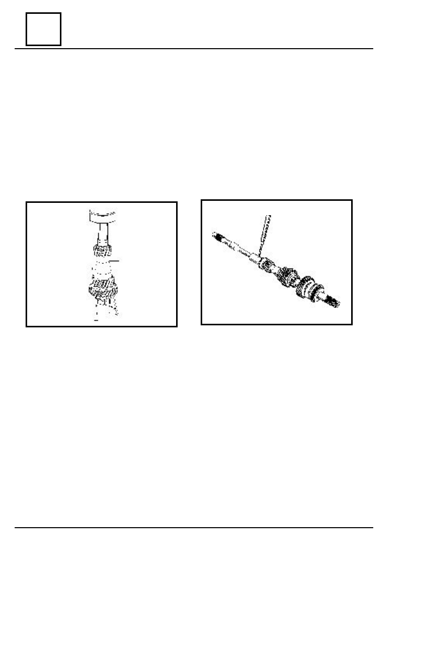
  PRIMARY  SHAFT  ASSEMBLING

Mount the biconical bearing.
Press the needle-roller bearing inner ring.
Mount the outside bearing ring together with its rollers casing.
Mount the lock washer.
Mount the clutch shaft ; place a new compensation washer between the end of the shaft, in

order to prevent the noise.

Mount the elastic pin by means of the  C.V. 31B mandrel.

REPAIR

MANUAL GEARBOX

21

21 - 31

 DIFFERENTIAL GEAR ASSEMBLING ( G.B. 365 and 51C )

Place the  following parts in the casing:

- the textolite washer ,with the lubricating grooves directed towards the propeller shaft

pinion ; use 1.96 - 2 mm thick washers. The 2.03 - 2.07 mm thick washers shall be used only
if  the clearance between the propeller shaft pinion and the differential pinion is very big.

- the propeller shaft pinion, lubricated with oil;
- the friction washers of the differential pinions;
- the differential pinions.

Mount the differential pinions shaft and center the pin shaft with the one in the casing.
Mount the elastic pin by means of the G.B. 31 B mandrel; the pin shall be introduced  about

5 mm in the differential gear casing.

 Lubricate the second propeller shaft pinion with oil and place it in the casing.

Mount the toothed crown on the differential

gear casing with new screws.

 Tighten the screws at the requiredoment ( 9

–11 daNm ).

REPAIR

MANUAL GEARBOX

21

21 - 32

Mount the differential bearings on a press.

  ADJUSTMENT OF THE CONICAL DISTANCE (G.B.365 AND 51 C)

The differential drive pinion is in the

 correct position, when its front is at  distance
A=59 mm from the toothed crown axis.

This position is obtained by mounting a

washer (1) of the adequate thickness between
the biconical bearing (2) and the differential drive
pinion shoulder(3).

CAS EXCEPTIONEL

There  may be situations when the value A=59

mm is not correct value for the pinion positioning.

The difference (X) between the actual

value and the value A=59 mm is marked on the
front side of the pinion near the number marked
for pairing with the toothed crown.

The value is given in hundredths of mm.

E

XAMPLE

 : X = 20 (0,2 mm)

In this situation ,the distance between the

conical mechanisms shall be  A + X. In a.m.
case:A +X = 59 + 0,2 = 59,2 mm

REPAIR

MANUAL GEARBOX

21

21 - 33


The checking of the conical distance is performed  by means of the CV239 - 01

control device, which materializes the toothed crown axis and by means of a spacer
CV 239 - 02, with the height H = 48,5 mm. The height (H) of the 48,5 mm spacer plus radius
(C) of the device axis of 10 mm represents: 48,5 mm + 10 mm = 58,5 mm.

The distance value (X) measured between the spacer and the pinion face shall be:

X = 59 mm - 58,5 mm = 0,5 mm (when the actual value  is A = 59mm).

Attach the right half crankcase on the support, with the separating plane upwards.
Place the secondary shaft.
Place the left (1) half crankcase and tighten it by means of several screws.
Tighten  the attachment spacer screws  on the half crankcase at the required couple.

     Introduce  the CV 239 -01 control device.

Place the CV 239 - 02 spacer at the end of

the differential drive pinion

Measure by means of a  thickness gauge

the distance (X) between the spacer and the
device shaft :
    1. The distance value measured is smaller
than the normal one  (0,5 mm) .In this case,
replace adjustment washer for the distance
between the  conical mechanisms with a thinner
one.
     2. The distance value measured is bigger than
the normal one (0,5mm).In this case,
replace the adjustment washer for the conical
distance with a thicker one.

The thickness of the adjustment washers is 1,8 - 3,8mm, every 10 hundredths of millimeter.
The measurement of the value (X) is performed by means of the speedometer endless

screw (G.B. 365 ) or the flange nut (G.B. 51 C ) tightened at the required moment
10 -12 daNm).

Take out the checking device.
Dismount : the spacer; the left half crankcase; secondary shaft.

REPAIR


Content   ..  54  55  56  57   ..