Dacia Pick-Up 1304/1305/1307. Service manual - part 40


  Index      Dacia     Dacia Pick-Up 1304/1305/1307 (Engine F8Q) - service and repair manual 2004 year


Search            


Content   ..  38  39  40  41   ..


Dacia Pick-Up 1304/1305/1307. Service manual - part 40


IGNITION AND  INJECTION

17

17 - 24

IMPORTANT:

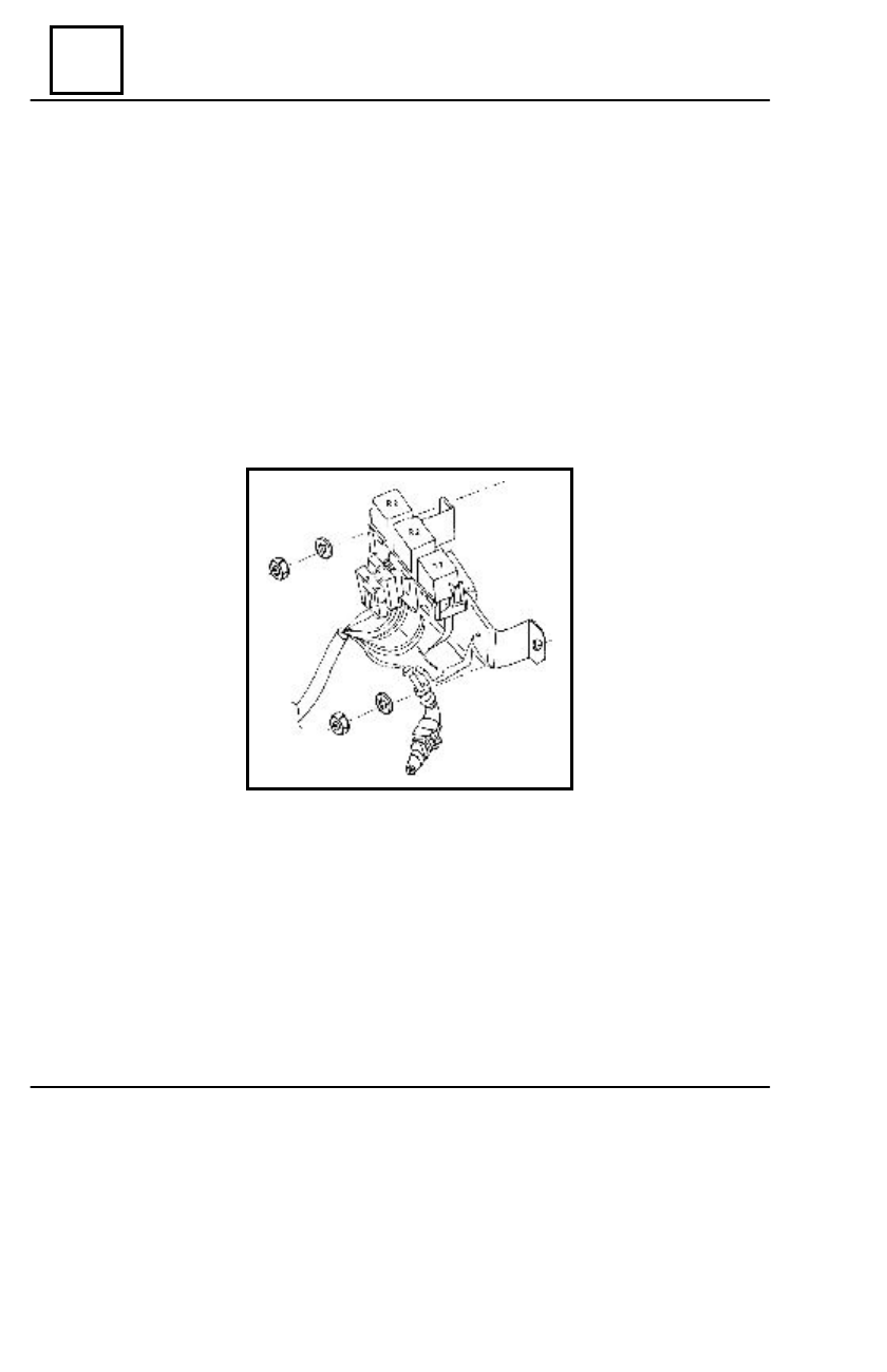
Two protecting relays and two fuses, placed on a fixed support on the front of the left mudguard

coating (front) electrically protect the injection system. The relays protect the supplying circuits
as follows:

- relay R1: for supplying the fuel electric pump the heating resistance of the oxygen rod an

the injector;

- relay R2: for supplying the computer (pin 17) and the injection witness of the vehicle

front panel;

- relay R3: for controlling the air conditioning compressor.

The plate fuses are 10 A; they are placed  on the supplying circuit  of the fuel electric pump

(S1) and of the oxygen rod (S2).

NECESSARY DEVICES FOR DIAGNOSIS AND MEASUREMENTS OF THE

SYSTEM PARAMETERS

- Voltmeter, ohmmeter, class 20000 Ù/V;
- Manometer for liquids, 0 – 4 bar, with T-connection;
- Tester SAGEM CLIP Dacia, KTS 300 or AT 520 with soft DACIA (MA 1.7) and

accessories for  series diagnosis;

- Marked vessel 0 – 2000 ml.

DIAGNOSTIC

17

IGNITION AND  INJECTION

17 - 25

PRELIMINARY CHECKING OPERATIONS

PRIOR THE DIAGNOSIS

The starting up  electric circuit components should be under  best conditions:

- Starter battery and cables;
- Fuel in accordance with the indications (without lead),  sufficient quantity

(minimum 5 l);

- Fuel filter according to the indications and correctly installed;
- Correct recirculation circuit (fuel vapors) with no clogging;
- Supplying circuit: good sealing between the  components, air  filter in  order;
- Acceleration cable should not be tensioned;
- The stroke of the acceleration pedal should be set to permit the complete opening of the

valve;

- The vacuum circuit for servo brakes and its valves should be in order;
- The engine should be in good mechanical order: compression tappet-levers setting, dis-

tribution steps, etc;.

- The spark plugs should be according to the constructor specifications;
- The control cables for fuel injection should be firmly fixed on the mass points (gearbox

case, direction column) and on supplying points (+12 V) – at starter;

- The exhausting track should be sealed mainly between the  evacuation gallery, down tube

and ë rod.

CONNECTING THE DIAGNOSIS TESTER

The diagnosis tester is connected to the vehicle injection cables, provided  with the  two ways

connector (AMP type, code 282189-1). This connector is placed on the left front mudguard
coating next to the relay and fuses block and fixed by a sealing clip. The
connector is provided with a protection gate valve. This protection is dismounted when connect-
ing the tester; the corresponding connector of the diagnosis tester is mounted in its place. The
tester is also connected to the 12 V battery of the vehicle.

WARNING !

 During the diagnosis the control lever of the gearbox should be on neutral and the

hand break should be pulled, to avoid the hazard risk.

 The tester-connecting table should be not in contact with the hot components of the

vehicle (collectors, exhausting system, etc.) or the moving components (engine shaft
pulley, water  pump pulley, and ventilation  propeller).

 When connecting the tester the contact key should be on “0”; at diagnosis the

contact key should be turned on “M” (contact ON).

DIAGNOSTIC

IGNITION AND  INJECTION

17

17 - 26

A. DIAGNOSIS BY SAGEM CLIP TESTER

The injection and ignition system diagnosis can be done by using the SAGEM CLIP tester,

after connecting it to the diagnosis plug of the vehicle and after its + 12 V supply from the battery
terminals and from the lighter plug.

The detailed description of the tester as well as the diagnosis soft DACIA installing and their

operation mode are written on the CD no.1 joint to the tester purchase.

Additionally this tester can be purchased as a complex variant (CLIP TEHNIC), which serves

to the diagnosis of the injection system; it also serves for physical measurements of different
parameters of the injection and ignition system components.

B. DIAGNOSIS BY TESTER KTS 300

The injection and the ignition system diagnosis can also be done by means of the “Pocket –

System Tester KTS 300 – Bosch”.

The tester KTS 300 executes the following operations:
* processing of the communication structures;
* processing of the communication by electronic control unit (computer);
* selection of the memorized damages;
* selection of helping menu (HELP);
* processing of damage code by comparing the real and the set up values;
* checking of acting elements (actuators test).
The tester is provided with the following keys:

- the keys 123, are used for selecting a line from the option list, proposed by the

program at a  certain moment;

- the keys > and < are used for shifting to the following screen or for returning to the

previous screen;

- the key H is the helping key for the following;
- screen lighting;
- meter stopping;
- displaying the data concerning the ignition and injection system;
- printer setting up;
- working speed setting for data transfer;
- the memorized data operations (printing, canceling).
- the key “ N  ” - is used for shifting to the previous level of the program;
- the key “ - - > ” for data memorizing;
- the key “ - - > ” for memorized data reading.

DIAGNOSTIC

17

IGNITION AND  INJECTION

17 - 27

After accessing the diagnosis menu by pressing the key >, a submenu is displayed, with the

following options:

- press key 1 for reading the memorized damages;
- press key 2 for displaying the real values of the checked measures;
- press key 3 for checking the functioning of the acting items;
- press key H for displaying the helping menu;
- press key N for returning to the diagnosis menu.

 In case of choosing the option “reading of the memorized damages”, when pushing  key “ 1 ”,

the screen will display a message with a total amount of the possible memorized damages.

When pressing key  “ > ”

the following message will be  displayed:

- the damage track;
- the damage type;
- the damage  code.

When pressing again the key  “ > ” further information about the damages type(sporadic or

permanent) will be displayed.

From now on the list of the memorized damages can be explored by pressing the key

“ > ”, when selecting a damage, one presses key “ 1 ” the damages possible causes can be
identified.

Each time one presses the key  “ N ” the previous message will be displayed.
After displaying the data about the last damage of the list by pressing the key  “ > ” the

computer sends a message to the user, asking if the damage has been rectified.

The following options are displayed:

- press key  “ ” for  YES;
- press key  “ 3 ” for NO.

When pressing key   “ 1 ”a message concerning the memorized damages will be displayed,

with two options:

- press key “ 1 ” for canceling it;
- press key “  ” for keeping it.

After pressing key


“ 1 ” the message


memorized damages cancelled” will be displayed.

For turning to the diagnosis menu, one presses key


 “ 3  ” or the keys  “ 1 ”, “  ” in a raw.

When choosing the option of action items checking (injector, electric-valve, idle

motion regulator etc.), one presses the key  “ 3 ” and two options for selection of the action items
will be  displayed:

- pressing key “ 1 ” - an action item is selected;
- pressing key  “ 3 ” the unit list is explored from the first on.

Once selecting an item its action is done under pulsing regime, for viewing it or for listening to;

the question “Is the  item  pulsing?” is displayed, with the following options:

- press key  “ 1 ” for YES;
- press key  “ 3 ” for NO.

DIAGNOSTIC


Content   ..  38  39  40  41   ..