Dacia Pick-Up 1304/1305/1307. Service manual - part 19


  Index      Dacia     Dacia Pick-Up 1304/1305/1307 (Engine F8Q) - service and repair manual 2004 year


Search            


Content   ..  17  18  19  20   ..


Dacia Pick-Up 1304/1305/1307. Service manual - part 19


10

10 - 42

ENGINE AND LOWER ENGINE UNITS

For all types of engines,the jackets shall be positioned as follows:

- the maximum difference between the heights of two adjoing jackets shall be

 maximum 0,02 mm,within the limit of the prescribed tolerance;

- the jackets shall be placed in growing order ( by steps ).

   After obtaining the correct height,the position of the jackets in the block is marked so that it
may be paired with the corresponding connecting rods.
   For the engines where sealing is done by “ Cu “ made gaskets,the checking is done with
gaskets fitted.
    Overheight of the gaskets over the gasket level : 0,05 – 0,13 mm. If the height of the jackets
over the gasket level is not within the prescribed limits, the jacket-block assembling values are  to
be checked.

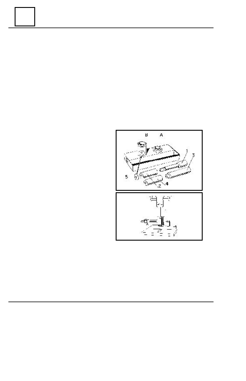
                                DISMOUNTING OF THE PISTON SHAFT

   The dismounting and mounting of the piston

shafts is performed by means of the MOT 255
device ,made of:

- support bushing of the piston upon

dismounting  the piston (A);

- support bushing of the piston upon

mounting (B);

- extractor mandrel (3);
- mounting mandrel (1);
- centering mandrel (2);
- connecting rod checking mandrel (4);
- washer (5).

Place the  old piston with the blades item on

the support bushing (A).

Introduce the extractor mandrel (3) and by

means of a press, dismount the shaft of the old
piston.

CONNECTIONG RODS PREPARATION

Check:

- the state and the aspect of the connecting rods;
- the setting of the cap on the connecting rod body; remove the burrs if any in order to

ensure a correct setting;

- the parallelism of the head and the foot;
- the connecting rod twist.

DISMOUNTING - MOUNTING

10

10 - 43

ENGINE AND LOWER ENGINE UNITS

NOTE:

If wear of the connecting rods is noticed or if the parallelism of the shafts is not

correct, the connecting rods shall be corrected or replaced.
   For the new connecting rods, a check shall be made so that they belong to the same
weight class (they shall not have the same colour marked on them).

                           PREPARATION OF THE PISTON SHAFT

Check if the piston shafts  rotate freely in the

corresponding pistons.

Mount shaft on the mounting  mandrel (1);

the pistons shaft shall freely rotate on the mandrel.

 Mount the centering mandrel (2) on the

mounting mandrel (1).

Grease the mandrel-piston shaft  assembly

with special grease containing MoS

2.

              PISTON –  CONNECTING

Use an electric  plate of  1500 W.

(electric oven)

 Heat the crosshead end of the connecting rod

in the furnace at a temperature of about 250°C
(10 – 15 minutes) in order to increase the bor-
ing of the connecting rod crosshead end by dila-
tation.

The temperature is checked by placing a piece

of tin (a) on the crosshead of the
connecting rods;  heat the connecting rods  until
the tin melts.

On the piston head there is an arrow marked

which must be oriented towards the flywheel.On
the oposite side of the piston there is a bladed
item on which the piston lay when the piston shaft
is mounted.

ROD PISTON SHAFT ASSEMBLY

DISMOUNTING – MOUNTING

10

10 - 44

ENGINE AND LOWER ENGINE UNITS

When assembling the piston with  the connecting rod,the  following instructions are to be

observed:

- place the piston with the bladed item on the bushing (B) of the piston shaft mounting device;in

this situation the arrow on the piston head shall be upwards oriented;

- place the connecting rod on the piston with the marking or with the slots for bushings oriented

towards  the right side of the worker; in this situation when mounting the assembly in the block
the arrow shall be oriented towards the flywheel and the marking on the connecting rod will be
on the opposite side of the camshaft.

NOTE: The following operations are to be performed very quickly to avoid the

 connecting rod cooling.

 When the connecting rods reached the tem-

perature of 250 °C ( the tin is melted):

- remove the tin from the crosshead end

of the connecting rod;

- place the connecting rod in the piston

observing the positioning indications of the latter;

- quickly introduce the mounting mandrel

(1) with the piston shaft until the
latter comes into contact with the bottom of the
support bushing;

-  dismount  the chuck  from  the piston shaft;

check if the piston shaft remains retracted as to
the piston disregard of the connecting rod position.

NOTE: On the bottom of the support bushing shall be placed a 1,5 mm.

Mount on the piston:

- the lubricating ring;
- the sealing rin with the marking “ TOP “

towards the piston head;

- the compression ring.

Abundantly lubricate with fresh oil the rings

and the piston;

Displace the rings  slots  at  120

 0

 ; 

 the slot of

the lubricating ring shall be obligatory on the side
of a fill of its channel and at 90 º as to the piston
shaft.

ASSEMBLING SET MOTOR

DISMOUNTING - MOUNTING

10

10 - 45

ENGINE AND LOWER ENGINE UNITS

Lubricate the jackets with fresh oil.
Mount in the jackets the piston-connecting rod assembly with the bushing:

MOT 502 for 102 engines;
MOT 655 for 106 engines.

When mounting, the connecting rod sides will be parallel with the flattenings made on the

jackets.

Mount the sealing gaskets on the jackets.
Mount the bushings on the connecting rods.
Place the connecting rod-piston-jacket assembly in the block ; observe the correct

positioning:

- cylinder (1) towards  the flywheel;
- the marking on the connecting rod opposite to the camshaft;
- the arrow on the piston head shall be oriented towards the flywheel.

Mount the the jackets maintaining device MOT 484.
Oil the the bushings and the crankshaft with fresh oil.
Place the connecting rods on the bearings and mount the caps.
Tihten the cap nuts at the required moment of 4.5 daNm  with   dynamometric wrench.
Check the correct rotation of the mobile assembly.
Dismount the device for jackets maitaining.
Mount:

- the oil pump;
- the oil sump;
- the cylinder head; adjust the tilters;
- the breaker-distributor; adjust the ignition.

Perform :

- oil filling of the engine;
- filling and aeration of the coolin system.

DISMOUNTING – MOUNTING


Content   ..  17  18  19  20   ..