Dacia Pick-Up 1304/1305/1307. Service manual - part 16


  Index      Dacia     Dacia Pick-Up 1304/1305/1307 (Engine F8Q) - service and repair manual 2004 year


Search            


Content   ..  14  15  16  17   ..


Dacia Pick-Up 1304/1305/1307. Service manual - part 16


10

10 - 30

ENGINE AND LOWER ENGINE UNITS

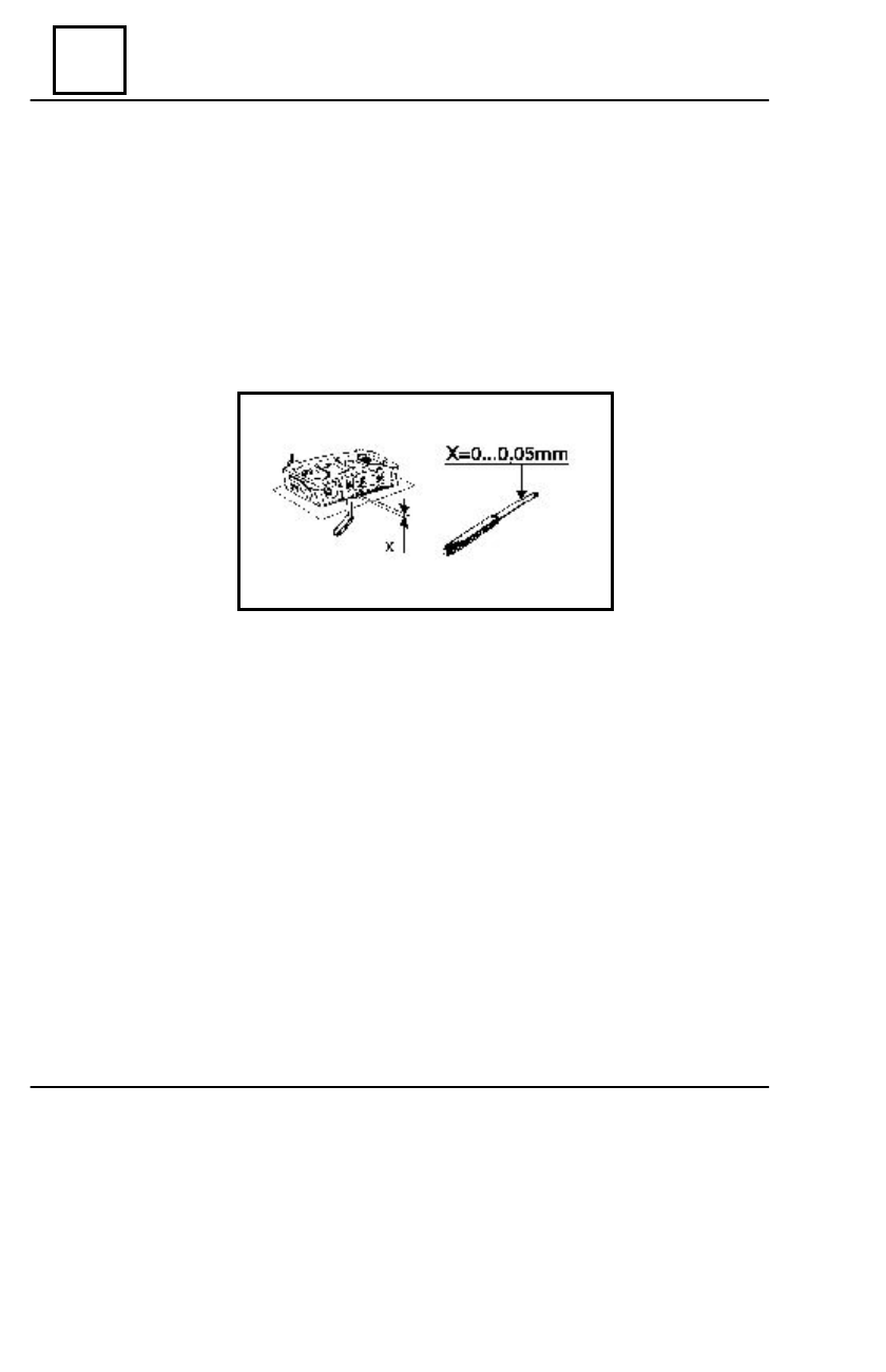
CHECK OF THE GASKET PLANE DEFORMATION

The checking of the deformation of the gasket plane is done by means of a ruler and of a set

of gauges.

The maximum accepted deformation is: x = 0,05 mm.
If the maximum deformation exceeds this value,the gasket plane is corrected by grinding.
Before grinding water pump and tilters platform are to be dismounted.
The cylinder head shall be carefully positioned on the grinding machine in order to observe the

parallelism of the surfaces.

The maximum addition that may be ground: 0,5 mm.
If by grinding,the minimum accepted height is exceeded, the cylinder head is to be replaced

because by  reducing the  height,the compression ratio is altered.

MOUNTING

Perform the dismounting operations in  the reverse order.

DISMOUNTING - MOUNTING

10

10 - 31

ENGINE AND LOWER ENGINE UNITS

PARTICULARITIES UPON RE MOUNTING

The contact surfaces of the gasket must be

clean.

The grease or antifreeze fluid must be

removed from the holes of the cylinder head fix-
ing screws by means of a.

This is necessary in order to obtain a

correct thightening of the screws and to avoid
the appearance  of casing cracks.

Dismount the  MOT 484 device for jackets

attachments.

Place the gasket with the marking “HAUT”

or “TOP” upwards.

Check if the hole in the gasket correctly overlaps the lubrication channel in the block.
Set the cylinder head and the fixing screws.
Tighten the screws at the required moment: 6,5 daNm.
Mount the tilters shafts in the holes where they have been dismounted.
Adjust the acceleration pedal stroke.
Fill and  aerate the cooling system.
Check and adjust the engine running.

CYLINDER HEAD REPLACEMENT

Dismount the cylinder head.

Dismount the spark plugs.
Dismount:

- the water pump pulley;
- the water pump;
- the ylinder head closing plate;
- the alternator support.

Set the  MOT 320 plate for vales support.

DISMOUNTING - MOUNTING

10

10 - 32

ENGINE AND LOWER ENGINE UNITS

Dismount the tilters platform.

 Compress the valves springs by means of the

MOT 382 compressing device.

Take out the lock half cotters,release the

spring,take out the upper tray,the spring and the
lower tray.

 Place the parts in order so that they may be

mounted back in the same place where they have
been dismounted from.

Remove the valves support plate,take out the

valves and  set  them in  order.

 Wash,clean and air blow the new cylinder

head.

Check the presence of the lubricating channels and valves state.
Perform the lapping of the valves on the cylinder head guiding ( this operation is also to be

performed when replacing the valves).

Mount the valves in the cylinder head and place the  MOT 320 valves support plate.
Place in  their previous  positions:

- sealing gaskets of the valves shafts;
- the lower valve heads ;
- the valve springs;
- half cotters.

NOTE:

 The valve springs are identical both for inlet and outlet.The springs are mounted

with the close coils towards the cylinder head.The end with close coils is marked with
green paint.

DISMOUNTING - MOUNTING

10

10 - 33

ENGINE AND LOWER ENGINE UNITS

Compress the springs by means of the MOT 382 compression device and mount the lock

half cotters.

Mount the cylinder head closing plate and the water pump with new gaskets.
Mount the alternator support.
Mount the cylinder head with new gasket observing the mounting instructions.
Mount the tilter shafts in the place where they have been removed from.
Adjust the tilters.
Mount the tilters cap.
Adjust the acceleration pedal stroke.
Fill and  aerate the cooling system.
Check and adjust the engine(ignition,carburation).
Retightem the cylinder head after 800 km of driving.

   VALVE SPRING REPLACEENT 


( on car )

Disconnect the battery.
Disconnect the acceleration cable.
Dismount the tilters cap.
Dismount the spark plug.
Mount the MOT 61 device for  valve

maintaining in the place of the spark plug.

Dismount the tilter shaft.

Compress the spring  by  means of  the

MOT 382 compressing device and take out the
lock half cotters.

 Take out the upper tray and the spring.
Clean the seat of the lower tray.
Place back  in  the  previous site:

- new spring ( with the close coils

towards the cylinder head,the end marked with
green paint);

- the upper tray.

DISMOUNTING – MOUNTING


Content   ..  14  15  16  17   ..