Dacia Pick-Up 1304/1305/1307. Service manual - part 7


  Index      Dacia     Dacia Pick-Up 1304/1305/1307 (Engine F8Q) - service and repair manual 2004 year


Search            


Content   ..  5  6  7  8   ..


Dacia Pick-Up 1304/1305/1307. Service manual - part 7


VALUES AND SETTINGS

07

07 - 10

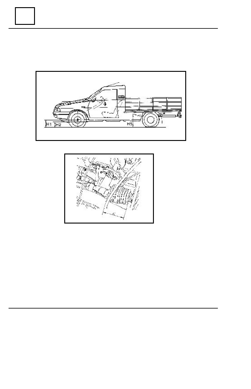
HEIGHTS UNDER CARRIAGE BODY

VALUES UNDER CARRIAGE BODY CONDITIONING THE ADJUSTMENT OP-

ERATIONS OF THE STEERING ANGLES.

H1 – the distance measured from the wheels center to the ground
H2 – the distance measured from the longitudinal girder lower part to the ground
H5 – the distance measured from the joint axis of the front leaf spring to the ground,

measured in the area of the lower arm attachment.

– this value is showing the position where the rack must reach in order to obtain the

middle point for  the steering rack.

VALUES AND SETTINGS

07

07 - 11

CONTROL VALUE OF FRONT AXLE ANGLES

A

djustable by

modification of

the tie-rod

length from

previous

mounting

Not adjustable

Not adjustable

Adjustable by

means of  the

tie rods rotation

-

H5 - H2 = 265
H5 - H2 =  255
H5 - H2 =  245
H5 - H2 =  235
H5 - H2 =  225

    H5 - H2 =  215
    H5 - H2 =  205

    H1 - H2 = 66

H1 - H2 =  62
H1 - H2 =  58
H1 - H2 =  54
H1 - H2 =  51
H1 - H2 =  47
H1 - H2 =  43

    H1 - H2 = 66

H1 - H2 =  62
H1 - H2 =  58
H1 - H2 =  54
H1 - H2 =  51
H1 - H2 =  47

  H1 - H2  =   43

Empty

Empty

VALUES

1

11'

1

0

28'

 1

0

45'

± 30'

2

0

02'

2

0

19'

        2

0

36'

        2

0

52'

Maximum Left / Right

difference = 1

0

         1

22'

         1

0

21'

1

0

20'

1

0

18'

± 30'

1

0

17'

1

0

15'

1

0

14'

Maximum Left / Right

difference = 1

0

8

01'

8

0

02'

8

0

03'

8

0

04'

±30'

8

0

05'

8

0

07'

8

0

08'

Maximum Left / Right

difference = 1

0

     Opening (toe-in)

       0

0

10’ 

±

 10’

    (for one wheel

        0

0

05’ 

±

 05”)

-

ANGLES

CASTER

CAMBER

BALL JOINT

TOTAL PARALLELISM

ELASTIC JOINTS 

BLOCKING

H5 - H2 = 260
H5 - H2 =  250
H5 - H2 =  240
H5 - H2 =  230
H5 - H2 =  220

    H5 - H2 =  210
    H5 - H2 =  200

    H1 - H2 = 66

H1 - H2 =  62
H1 - H2 =  58
H1 - H2 =  54
H1 - H2 =  51
H1 - H2 =  47
H1 - H2 =  43

    H1 - H2 = 66

H1 - H2 =  62
H1 - H2 =  58
H1 - H2 =  54
H1 - H2 =  51
H1 - H2 =  47

  H1 - H2  =   43

Empty

Empty

POSITION OF THE VEHICLE

ADJUSTMENTS

1304

1307

COMMERCIAL U 75 DRIVE (1304, 1307)

VALUES AND SETTINGS

07

07 - 12

CONTROL VALUE OF FRONT AXLE ANGLES

 Steering box positioning 


6 – 7,75 on the scale

By means of

   T.F.246

eccentrics


Steering rack central

C=65mm

By means of 

the

point

   steering whe

el

rotation

ANGLES

POSITION OF THE VEHICLE

ADJUSTMENTS

1304

1307

VALUES

OTHER  STEERING SYSTEM VALUES TO BE RESPECTED

VALUES AND SETTINGS

07

07 - 13

CONTROL VALUE OF FRONT AXLE ANGLES

COMMERCIAL U 75 / 4X4 DRIVE (1304, 1307)

 Adjustable by modifi-

cation of the tie-rod

length from previous

mounting

Not adjustable

Not adjustable

Adjustable by

means of  the tie

rods rotation

 H5 - H2 = 265
 H5 - H2 =  255
 H5 - H2 =  245
 H5 - H2 =  235
 H5 - H2 =  22

H5 - H2 =  215

 H5 - H2 =  205

    H1 - H2 = 66

H1 - H2 =  62
H1 - H2 =  58
H1 - H2 =  54
H1 - H2 =  51
H1 - H2 =  47
H1 - H2 =  43

    H1 - H2 = 66

H1 - H2 =  62
H1 - H2 =  58
H1 - H2 =  54
H1 - H2 =  51
H1 - H2 =  47
H1 - H2 =  43

Empty

Empty

1

11'

1

0

29'

 1

0

46'

± 30'

2

0

02'

2

0

19'

         2

0

36'

         2

0

53'

Maximum Left / Right

difference = 1

0

1

21'

1

0

20'

1

0

19'

1

0

18'

± 30'

1

0

16'

1

0

15'

1

0

13'

Maximum Left / Right

difference = 1

0

8

01'

8

0

02'

8

0

03'

8

0

04'

±30'

8

0

05'

8

0

07'

8

0

08'

Maximum Left / Right

difference = 1

0


Opening (toe-in)

-0

0


16

0


±

 10

0

(for one wheel

-0

0

08’

±

 05’

)

-

ANGLES

CASTER

CAMBER

PIVOT

TOTAL PARALLELISM

ELASTIC JOINTS BLOCKING

H5 - H2 = 260
H5 - H2 = 250
H5 - H2 = 240
H5 - H2 = 230
H5 - H2 = 220

    H5 - H2 =  210
    H5 - H2 =  200

    H1 - H2 = 66

H1 - H2 =  62
H1 - H2 =  58
H1 - H2 =  54
H1 - H2 =  51
H1 - H2 =  47
H1 - H2 =  43

    H1 - H2 = 66

H1 - H2 =  62
H1 - H2 =  58
H1 - H2 =  54
H1 - H2 =  51
H1 - H2 =  47
H1 - H2 =  43

Empty

1304

1307

POSITION OF THE VEHICLE

ADJUSTMENTS

VALUES

BALL JOINT

-

Empty


Content   ..  5  6  7  8   ..