Peugeot 1007 (2008 year). Manual - part 8
7
106
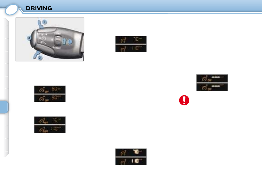
Operating fault
If a speed limiter malfunction occurs,
the speed is replaced by fl ashing
dashes. Contact a PEUGEOT dealer
to have the system checked.
Activating/deactivating the limiter
Switch the speed limiter on by
pressing button 4 .
Programming
Place the dial 1 in the LIMIT posi-
tion. The limiter is not yet active.
By default, the display indicates
the last speed programmed:
Return to normal driving
Turn dial 1 to position "0" : the
speed limiter mode is deselected.
The display returns to the distance
recorder.
In the event of a steep descent
or sharp acceleration, the
speed limiter will not be able
to prevent the vehicle from
exceeding the programmed speed.
In any event, the speed limiter cannot
replace the need to observe speed
limits, nor can it replace the need for
vigilance and responsibility on the
part of the driver.
The driver must remain alert and stay
in complete control of his vehicle.
To prevent the mat from becoming
caught under the pedals:
-
ensure that the mat is positioned
correctly.
-
never fi t one mat on top of
another.
Set the speed value by pressing but-
ton 2 or 3
(e.g.: 70 mph (110 km/h).
You can then change the programmed
speed using buttons 2 and 3 :
-
by + or - 1 mph (1 km/h) = short
press,
-
by + or - 5 mph (5 km/h) = long
press,
-
in steps of + or - 5 mph (5 km/h) =
maintained press.
Exceeding the programmed
speed
Pressing the accelerator pedal to
exceed the programmed speed will
not have any effect, unless you press
the pedal
fi rmly passing the point of
resistance .
The speed limiter is deactivated tempo-
rarily and the programmed speed,
which is still displayed, fl ashes.
Returning to the programmed speed,
by means of intentional or uninten-
tional deceleration of the vehicle,
cancels the fl ashing automatically
and reactivates the speed limiter.
Switch the speed limiter off by
pressing button 4 : the display
confi rms that it is off (OFF).
Switch the speed limiter back on
by pressing button 4 again.