Peugeot 307 Break Dag (2007 year). Manual - part 9
10
116
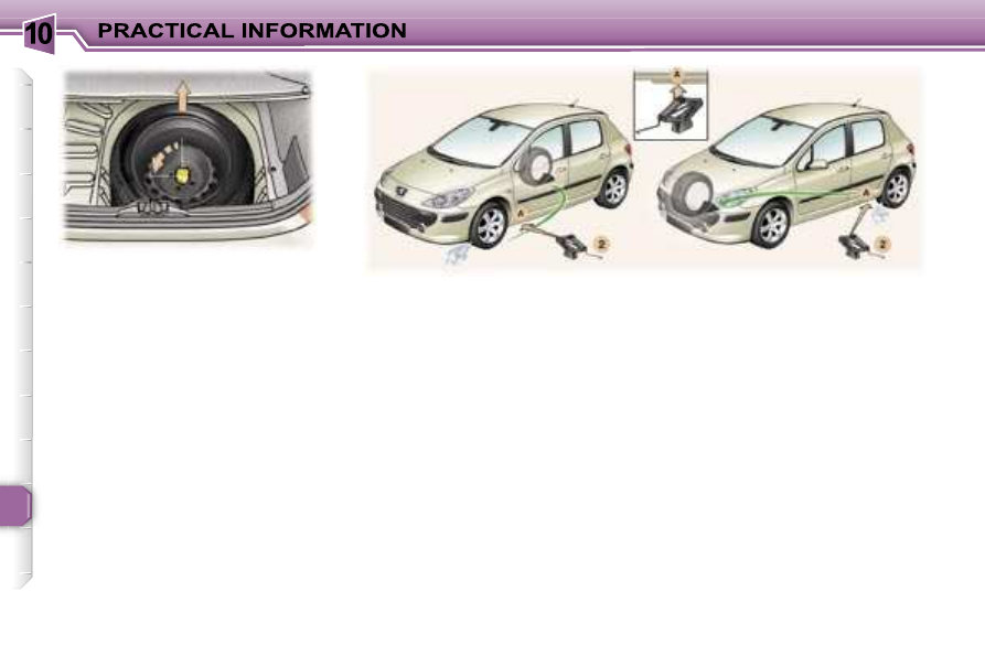
Removing the wheel
If necessary, place a chock under
the wheel diagonally opposite to
the one to be changed.
Remove the trim, using the wheel-
brace
1, pulling at the valve pas-
sage hole.
Loosen the wheel bolts (for vehi-
cles fitted with alloy wheels, re-
move the chrome trim first. See
paragraph on 'Special features of
alloy wheels').
Place the jack
2 in contact with one
of the four locating points
A on the
sub-frame (the one which is clos-
est to the wheel to be changed).
Extend the jack
2 until its base is
in contact with the ground. Ensure
that the centre line of the base of
the jack is straight above the lo-
cating point
A used.
Raise the vehicle.
Unscrew the bolts and remove the
wheel.
Fitting a wheel
Position the wheel using the cen-
tralising tool
3 to assist you.
Tighten the bolts by hand and re-
move the centralising tool.
Partly tighten the bolts using the
wheelbrace
1.
Fold the jack
2 and remove it.
Fully tighten the bolts using the
wheelbrace
1.
Replace the wheel trim, starting
by placing the wheel trim notch
opposite the valve, and press it on
using the palm of the hand.
Extracting the wheel
Unscrew the yellow central bolt a
quarter turn.
Raise the spare wheel towards
you from the rear.
Remove the wheel from the boot.